Creating Custom Shapes in Flux
Create custom shapes for pads, symbols, silkscreen and board layout.

Overview
Some elements come in many different forms. IC footprints, antennas, and other connectors all may have specific pad-shape requirements, some symbols require many different shapes and board layouts have all sorts of different requirements.
In this tutorial, we'll cover how to create and add custom shapes to many different elements, including pads, silkscreen, board layout and zones.
Creating a Custom Shape
Flux supports DXF and SVG files as input for custom shapes. You can use any CAD or drawing tool to generate these shapes, but if you're not used to creating shapes we'd suggest you start with Onshape for DXF files or Inkscape for SVG files.
Shape Requirements
Depending on what element you'll be using the shape in, there might be specific requirements:
Symbols
- Every shape and line should be white, with 1px stroke width and no fill
- Pins are typically 10 to 18 pixels long
- Basic parts (i.e. resistors, caps, transistors) typically fit in a 40x40 px area. Larger, more complicated parts, such as ICs, may require a larger area
Pads, Zones and Layout
- Lines need to form a single closed shape
- Do not include any holes or cutouts. Those will need to be added afterward using holes
- Multiple lines need to be converted into a single polyline
Silkscreen
- No specific requirements
Creating DXF Shapes with Fusion360
The video below covers how to create DXF shapes using Fusion 360 for a symbol, but the same process can be used to create a shape for any other element (pad, footprint and layout):
Creating SVG Shapes with Inkscape
Inkscape is an open source tool, and it's available for most platforms. Even if you're unfamiliar with SVG files, the steps in this tutorial should be enough to help you create your first shape.
The video below covers how to create a custom symbol shape, but the same process can be used to create a shape for any other element (pad, footprint and silkscreen):
Importing the Shape into Flux
There are two ways of adding generated shapes into Flux:
- Using an asset: This works on every scenario, both for DXF and SVG files
- Injecting code directly on a shape rule: This option works only for SVG shapes, and cannot be used for symbols
Option 1: Using an Asset File
You can use an external DXF or SVG file to dictate the shape of a pad. This is a two-step process; first, you must add the SVG or DXF as an asset and then link the asset to the target pad.
Step 1: Adding DXF/SVG Files as Assets
To add an external file as an asset:
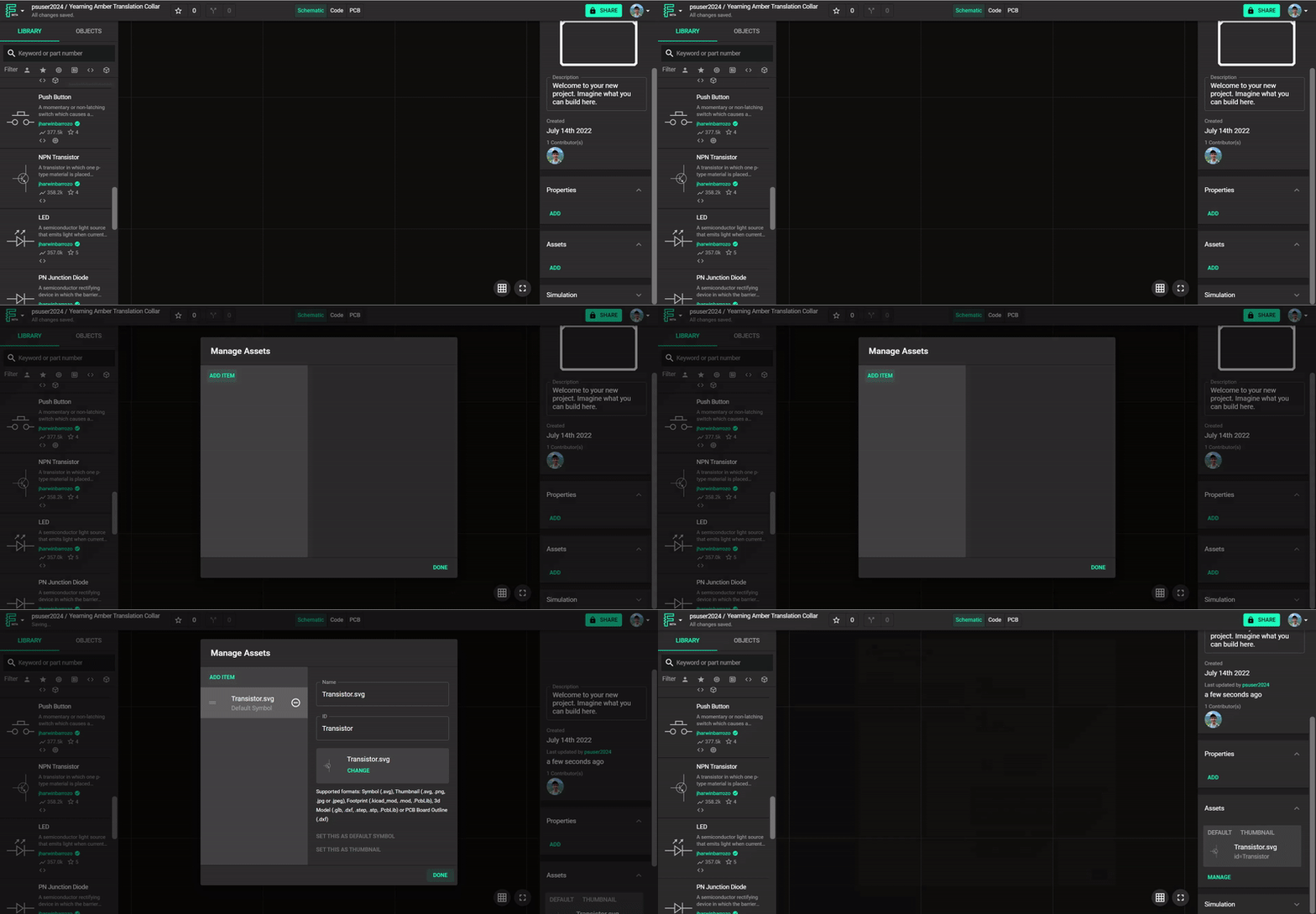
- Make sure no object has been selected (click on the empty canvas)
- On the right drawer, scroll down until you find the assets panel. Open it and click on "Add" (or "Manage"). This will open the assets dialogue.
- Then click on "Add item" and select the file from your local drive.

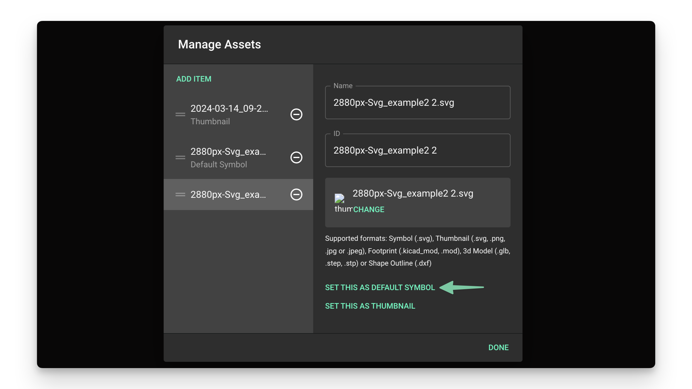
If you're creating a custom symbol and have added multiple assets, click the "Set this as default symbol" button.

Step 2: Link the Asset to the Target Element
Once you've added the SVG or DXF file to the asset list, then link the asset to the target element.
Skip this step if you're creating a custom symbol. You can now go back to the symbols tutorial.
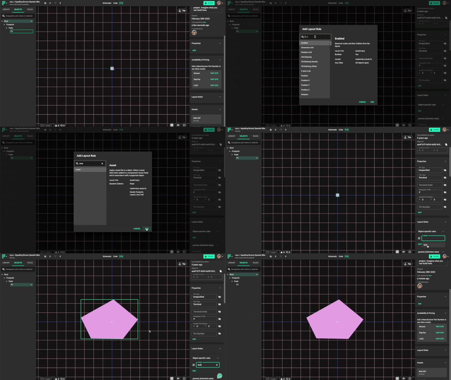
To link an asset to an element:
- Select the element you want to make into a custom shape
- Silkscreen: Object type -> Silk Line
- Board shape: Object type -> Layout
- Pad: Object type -> Pad
- Zone: Object type -> Zone
- Locate the "Layout rules" drop-down menu on the right-side panel
- Find the "Object-specific rules" submenu
- Click on "Add"
- Find and add the "Asset" rule
- Inside the "Asset" text box, select the SVG/DXF file added in the previous step from the list

Example: adding an asset to a pad.
Step 3: Scaling an Asset
By default, Flux assumes the imported file will be in meters. You might need to adjust the scale of the asset using a scale rule.
Option 2: Using the Shape Rule for SVG Code
Some elements (pad, layout, line, zone) allow you to add SVG code directly into the rule. Custom-shaped symbols can only be created via the asset method. To add the SVG code directly into a shape rule:
- Open the PCB editor
- Select the element you want to convert to a custom shape
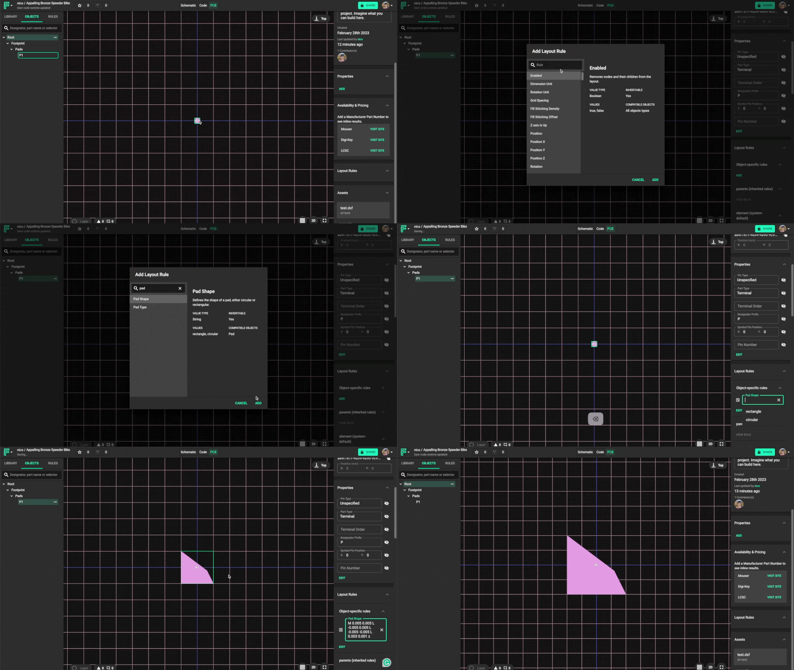
- Locate the "Layout rules" drop-down menu on the right-side panel
- Find the "Object-specific rules" submenu
- Click on "Add"
- Find and add the corresponding "Pad shape", "Line shape", "Zone Shape", or "Layout Shape" rule
- Inside the rule's text box, paste the SVG code. See the SVG code below as an example
M 0.005 0.005 L -0.005 0.005 L -0.005 -0.005 L 0.003 0.001 z
Example: adding SVG code directly to a Pad Shape rule
What's Next
Now that you understand how to create and use custom shapes in Flux, you might want to explore:
- Board Outline Shape Tutorial - Apply custom shapes to your board outline
- PCB Routing Tutorial - Learn how to route your PCB with custom pad shapes
- Component Placement - Learn how to efficiently place components with custom shapes
- Layout Rules Tutorial - Understand how to use rules to control your PCB design