Working with Ground Signals in PCB Design
Work efficiently with multiple types of grounds with little configuration, from basic single-ground applications to multiple shielding or isolated grounds.
Overview
In Flux, working with a single ground is very straightforward. Add a standard ground symbol to your schematic and simply wire it up. Flux will then take care creating a ground plane for you.
Working with multiple grounds is also straightforward in Flux, but simply requires adding a portal with a ground symbol for additional secondary grounds. We'll be breaking down what this is and how it operates further below.
Having multiple grounds in your PCB might be useful in cases where you’d like to separate analog and digital circuitry, separate power and signal ground, specific RF grounds, mixed-signal systems, or specific shielding. We’ll be covering the following points on using ground in Flux
- How to create a single basic ground with accompanying ground plane (aka copper field)
- How ground is tied to copper fields and how to manage it.
- Adding multiple grounds so they work with ground fills in the PCB editor.
- How DRC works with multiple copper fields
Getting Started with Basic Grounding
Let’s take the simplest example of a battery connected to a resistor, as shown below. Just like any other component, you can drag a basic ground symbol from the library and wire it into your circuit.

When you add a GND symbol, Flux will auto-generate a ground fill. Adding a GND symbol will generate the following:
- A GND net is generated in the PCB outline
- The net contains a fill element (which is the ground fill)
- Stitching vias are generated
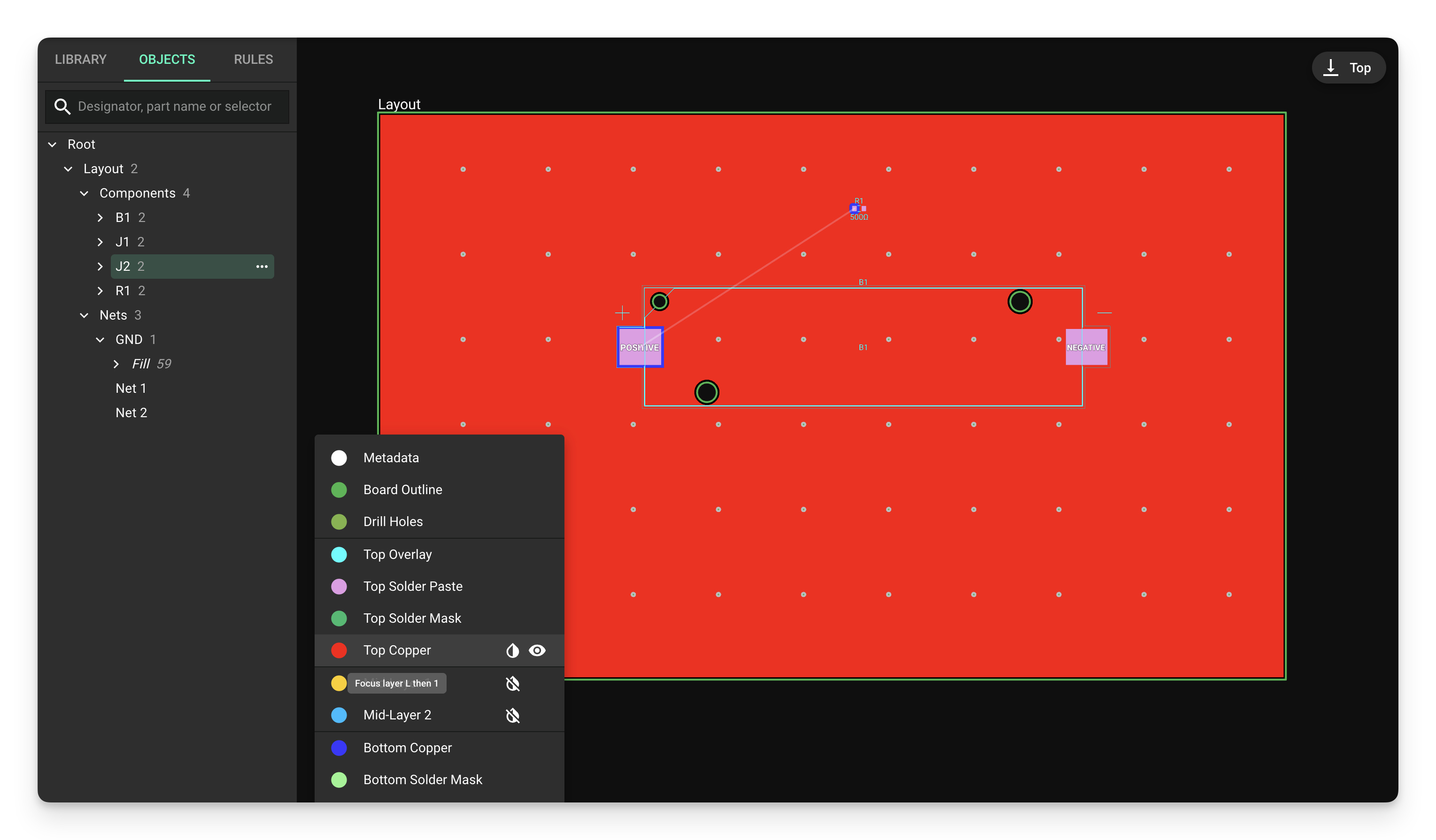
Flux will automatically generate the ground fill on a layer and will wrap around components, different nets, and traces. If the ground fill is already generated, as you route your board, it will automatically update, so don’t worry!
Note: You can hide the ground fill, but it will not be deleted if your schematic has a GND component. If hidden, in exporting your board, the ground fill will also be exported regardless.
Working with Multiple Grounds
Schematic
Suppose you are designing a circuit with multiple grounds. For example, if you add a USB receptacle with a shield pin, you may want to handle the shield ground differently than the primary circuit’s ground. The solution to adding a second ground in Flux is through a portal with a ground symbol (Ground Portal) in the schematic.
Portals with ground symbol (ground portals) allow you to have multiple ground signals in your circuit
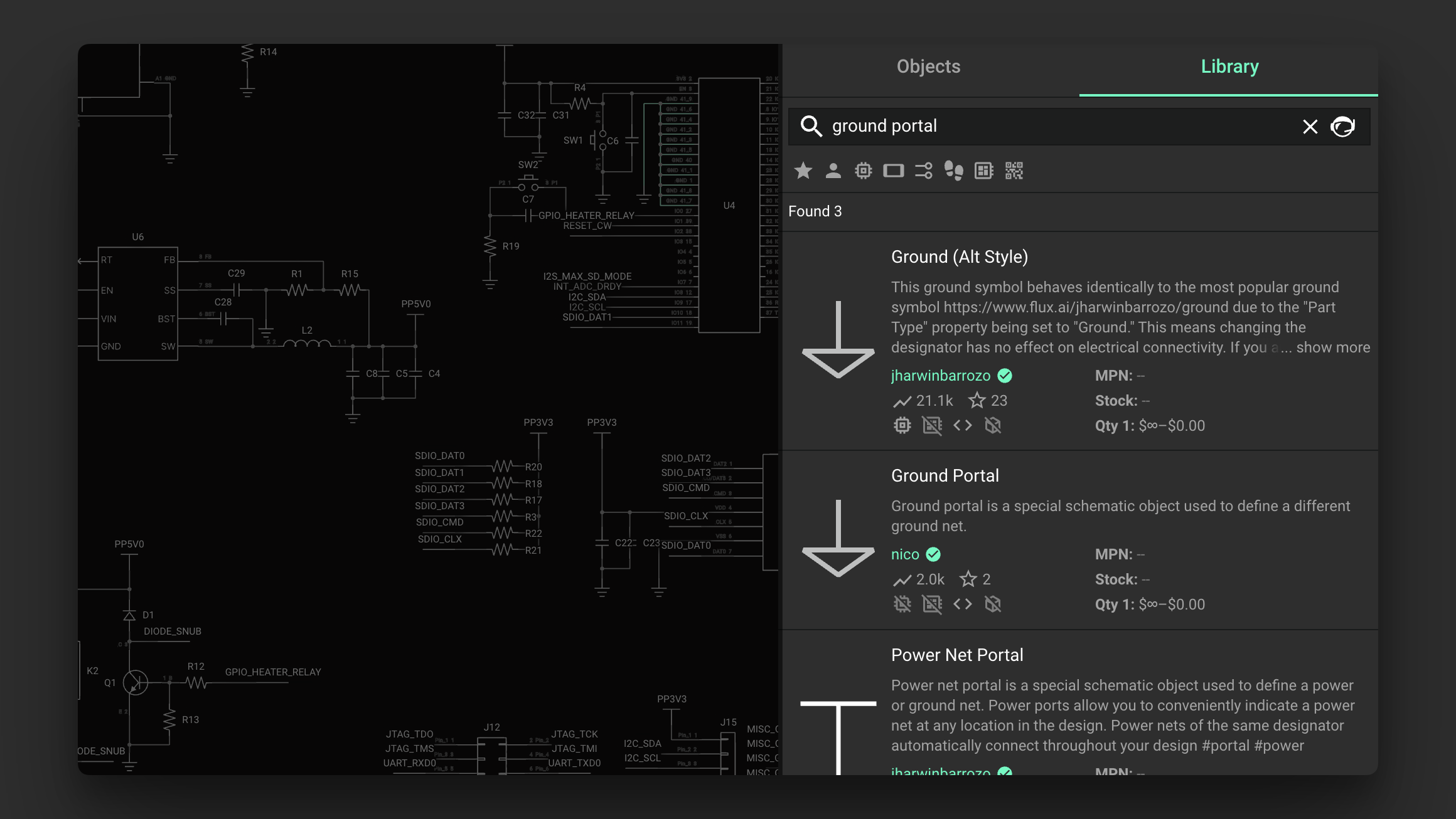
From the parts library on the left, drag in a portal with a ground symbol to your schematic as a secondary ground. (Search for it in the library!)
- Ground portals behave identically to normal portals (discussed below) and differ solely in their visual appearance as a symbol in the schematic.
Once you’ve connected your ground portal component, connect the secondary ground to the primary through your desired filter/bypass capacitor or any other filter network, as necessary.
Ensure that all ground portals share the same name so they will then share the same secondary ground net in the PCB editor.
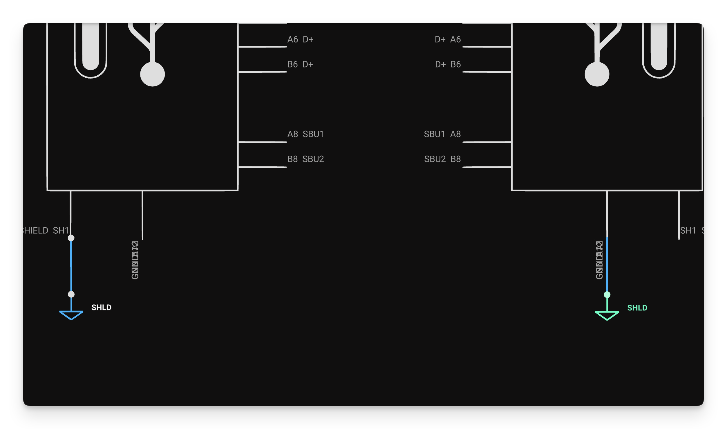
Adding a standard portal component will achieve the same effect but will not be as visually clear in the schematic. Having all components associated with ground visually connected to a ground symbol is good circuit design practice, making the schematic easier to understand. For these reasons, adding a ground portal over a standard portal allows your schematic to be easily understood as a ground pin.
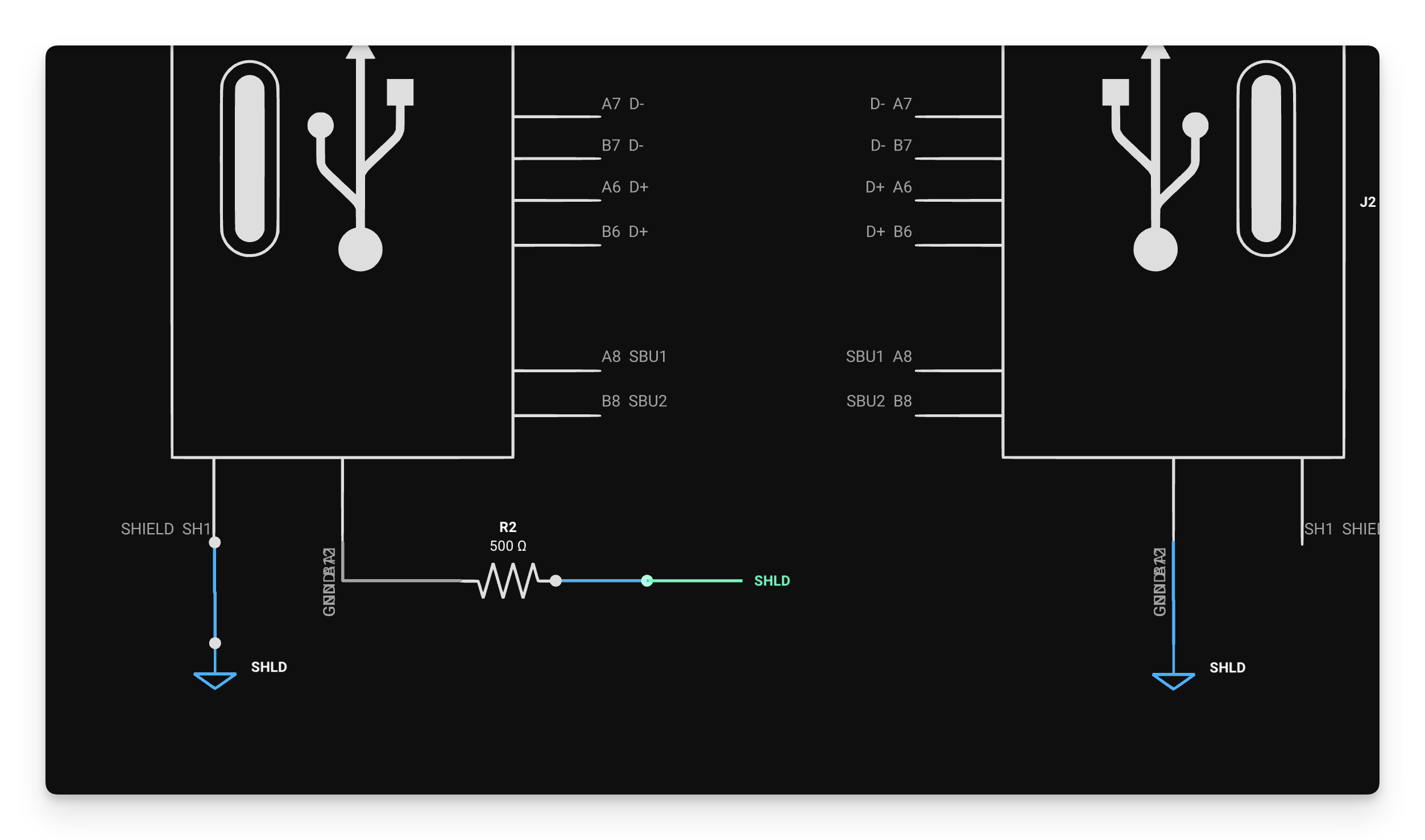
A ground portal is equivalent to a standard portal, but contains a ground symbol for easier identification.
Why Can’t I Rename Multiple Primary Grounds?
If you copy-pasted the primary ground and renamed it something like shield_gnd, they will remain connected as the same ground. Copy-pasting and renaming is a common method in other tools for creating additional isolated grounds but does not work in Flux.
In the PCB editor, both grounds will then appear as part of the same net (GND), and they will not be isolated from each other when Flux auto-generates the ground fill. This is because the primary ground component and copy-pasted renamed ground have a "Part Type" property set to Ground.
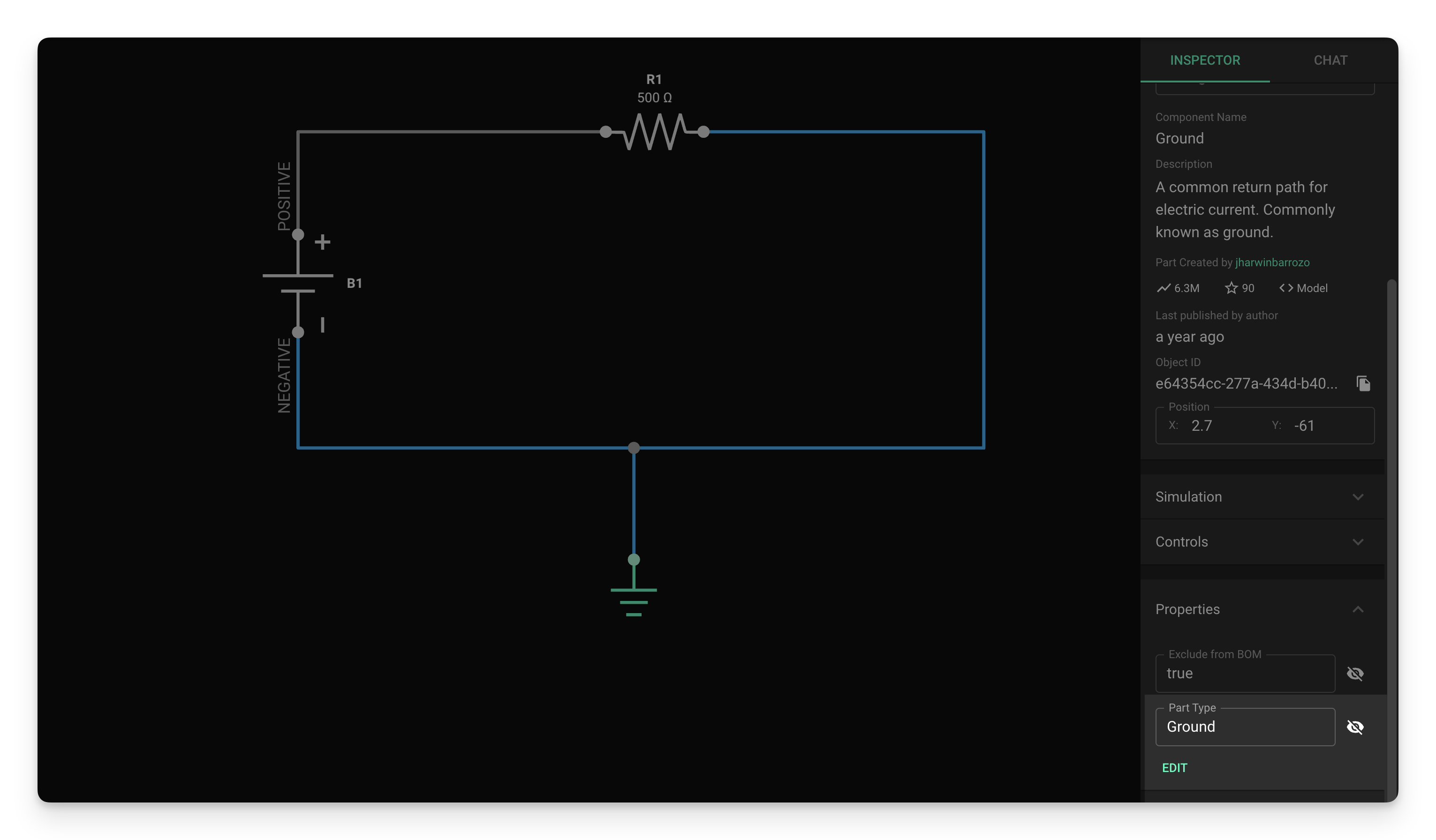
As both components have the same “part type,” they have the unique property that auto-generates via stitching and the same copper fields. You cannot have more than one differently-named component with a part type set to ground. Otherwise, any property you add with a part-type ground will auto-connect with your primary ground, regardless of the name.
PCB Layout
As we’ve discussed, any component with a part type set to ground will be auto-added to the pre-existing GND fill and share the same copper fill and via stitching. To generate unique copper fills and via stitching for an additional ground, follow the steps outlined below:
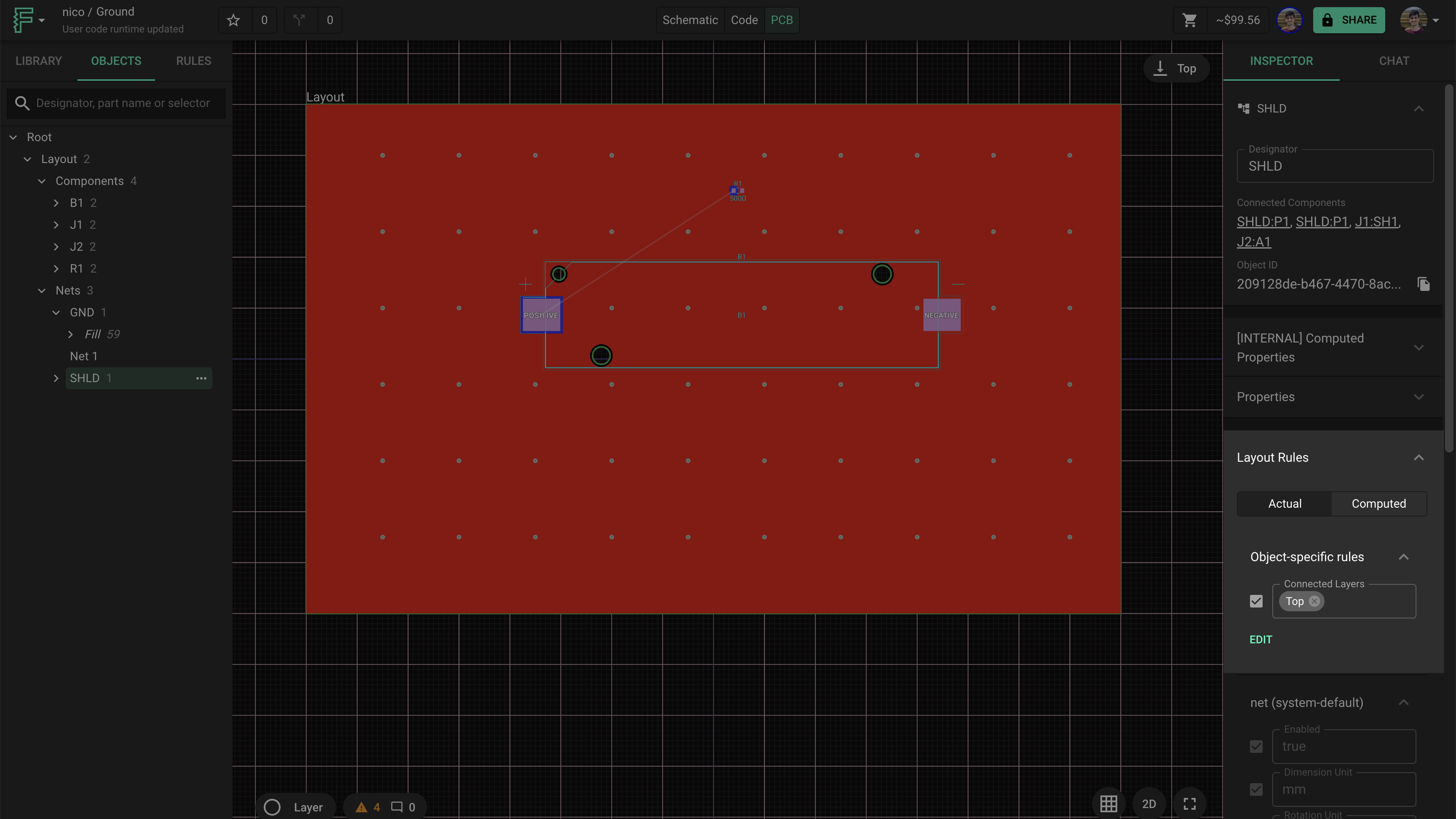
- In your schematic, select the ground net by clicking on it.
- Then, switch over to the PCB editor and notice it is now highlighted in the object tree. Now, you can give a unique name to your net associated with the second ground (e.g. SHLD_GND)
- Select your newly named net in the PCB editor and add a connected layer rule_._
- This adds a copper fill to any layer specified.
- You can set it to All, Top, Mid-layer 1, Mid-Layer 2, etc., as desired.
- Note that after applying this rule, you may get a DRC error, handled below.
Handling DRC Error for Multiple Copper Fills
In setting your connected layer rules as discussed above to generate a unique copper fill for your secondary ground, you may encounter the following DRC error: board layer with multiple copper fills. This happens because there are now two nets (primary ground and secondary ground) that want to create a copper fill on a given layer. Below is an example with a pre-existing primary ground plane and a secondary ground plane both attempting to create a copper fill on the top layer.

The solution is to ensure that your connected layers are set to a layer that doesn’t already contain a primary GND plane. In other words, set the secondary ground plane to a different layer than the primary. Note that after making any changes with ground planes given that you have already wired some of your board, you will need to rewire your PCB by adding vias and wires to connect them to the new isolated plane.
Customizing Symbols
Suppose you want to add another ground on top of the two pre-existing ones, such as an earth-ground. Simply add another ground portal and give it a unique name, such as EARTH_GND. Because the names are different, the EARTH_GND will be isolated from the SHLD_GND and the primary ground.
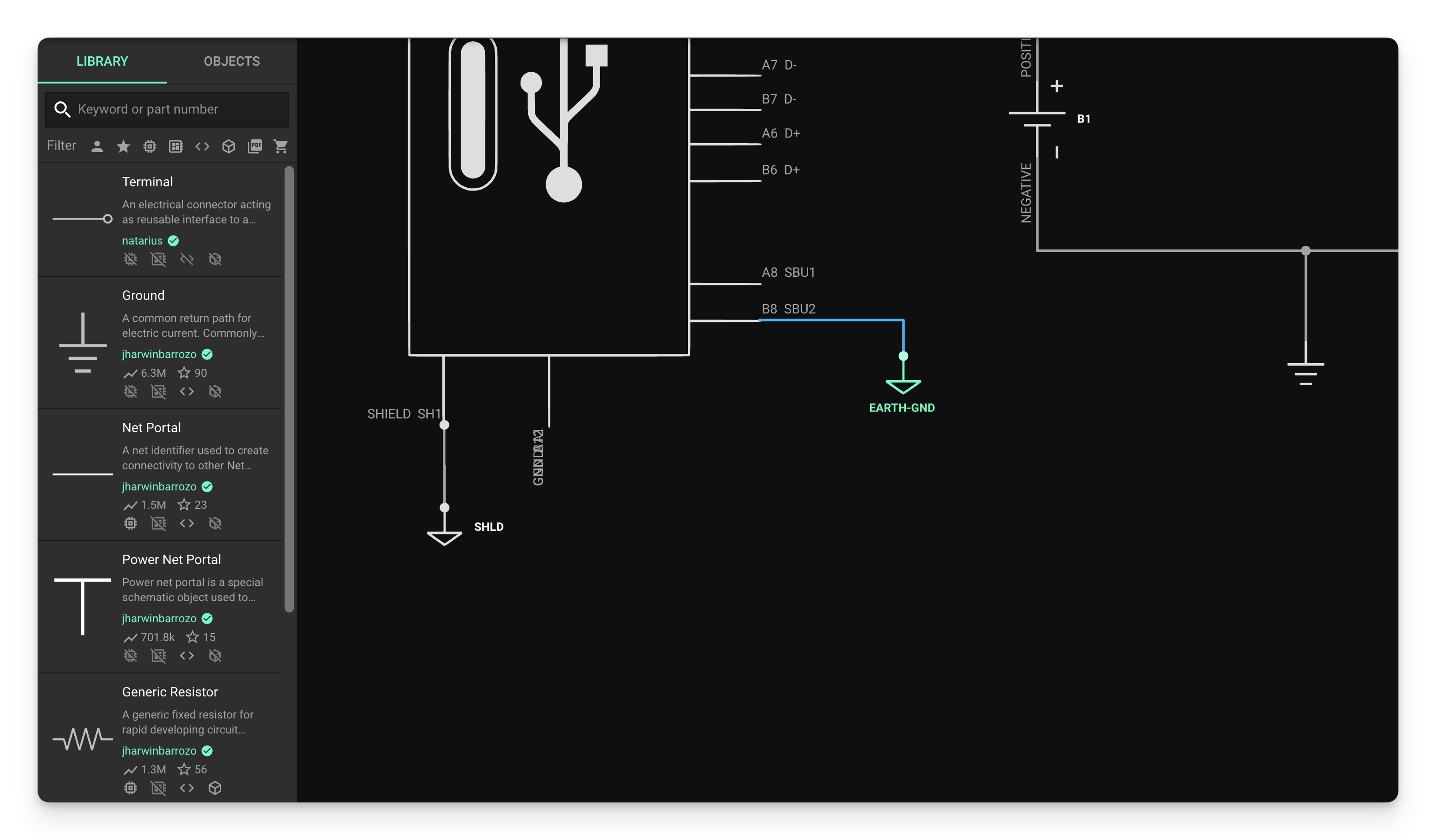
Want to make your own ground portal symbol? Simply clone the ground portal and add a custom symbol.