In this final section, we’ll transition from schematic to layout, build your stackup, route traces, and manage ground and power planes.
Overview
If you’re in a hurry, here’s what you need to know:
Netlist and ECO do not exist in Flux. Schematic and PCB data are automatically synchronized.
Everything you'll find on the layout properties panel in Kicad, in Flux you can find in the inspector tab (right side of the screen) under rules. Learn more.
Flux automatically creates ground fills (planes) connected to ground. Learn more.
Going from Schematic to Layout
In KiCAD
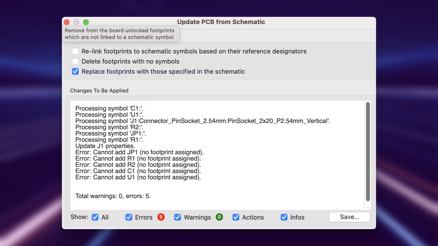
To forward your schematic changes into the layout editor, you need to use the “Update PCB from Schematic” menu. The process involves generating a Netlist and using an ECO to sync.
In Flux
The schematic and layout editors are bidirectionally synchronized in real time. Bidirectional Sync means any changes in the schematic automatically update the PCB layout and vice-versa without the need to create a netlist or ECO.
Real-time synchronization eliminates the risk of design discrepancies.
Creating a Stackup
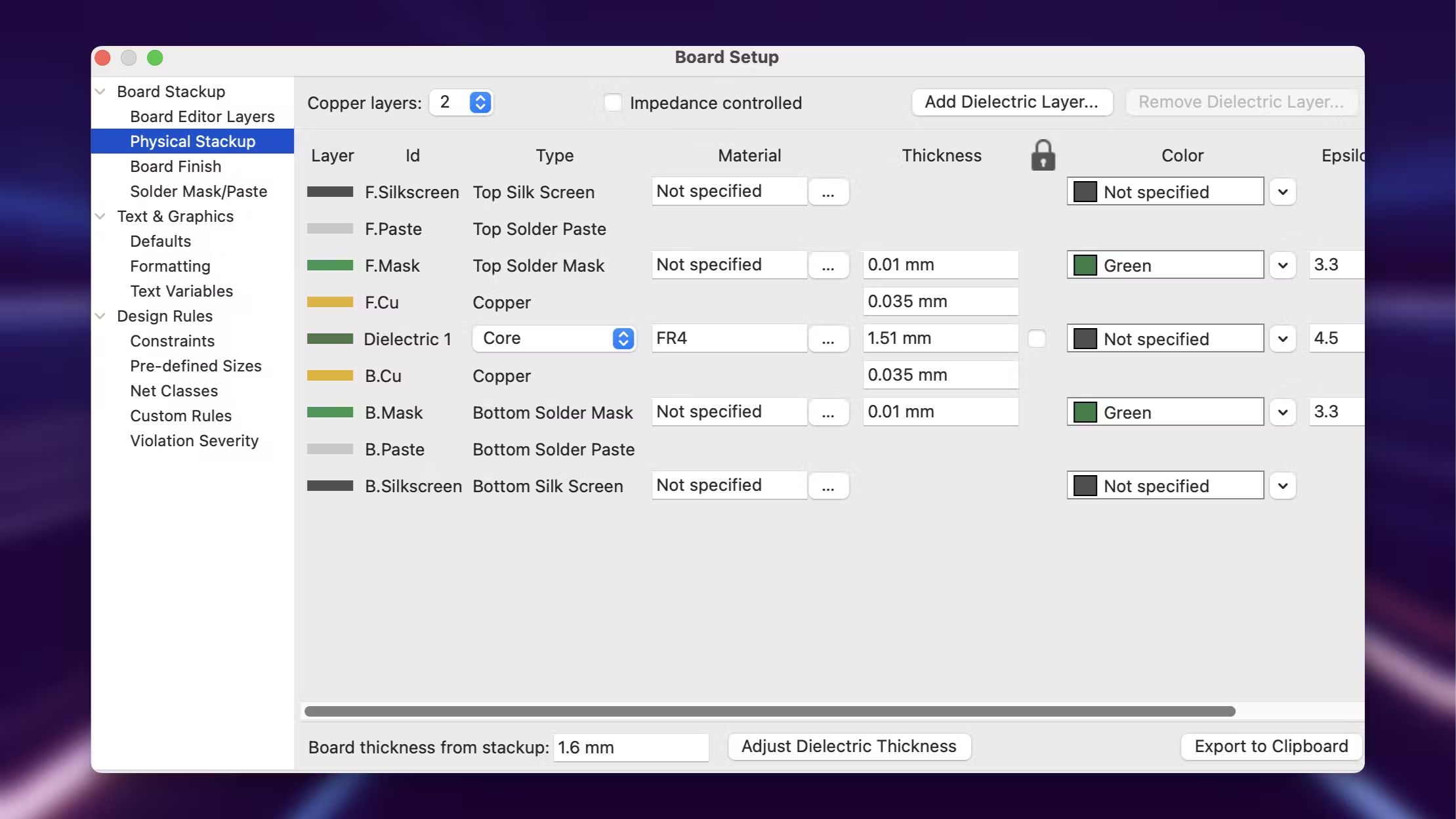
In KiCAD
Layer properties are defined through the Properties menu.
In Flux
The stackup is a characteristic of the layout object. You can think of the layout object as the actual PCB, so things like board layout or stackup are modified through the layout object via rules.
Rules are one of the most important concepts in the PCB editor. They are similar to KiCad’s footprint properties, but they act on every object (footprints, pads, traces, layout, etc). You can learn more about rules here.
To modify your stackup:
Select the Layout object
Find the “Layout Rules” section under the “Inspect” panel on the right.
Click on “edit” then “add” and find the rule called stackup
Select a stackup template from the list, or click on the pencil icon to create a custom one.
The layout object can also be modified to create different board shapes. Learn more.
Routing Traces
In KiCAD
To create traces on KiCAD, you need to select the trace tool and then start routing. Design rule checks (DRC) need to be manually run, often times after routing is finished.
In Flux
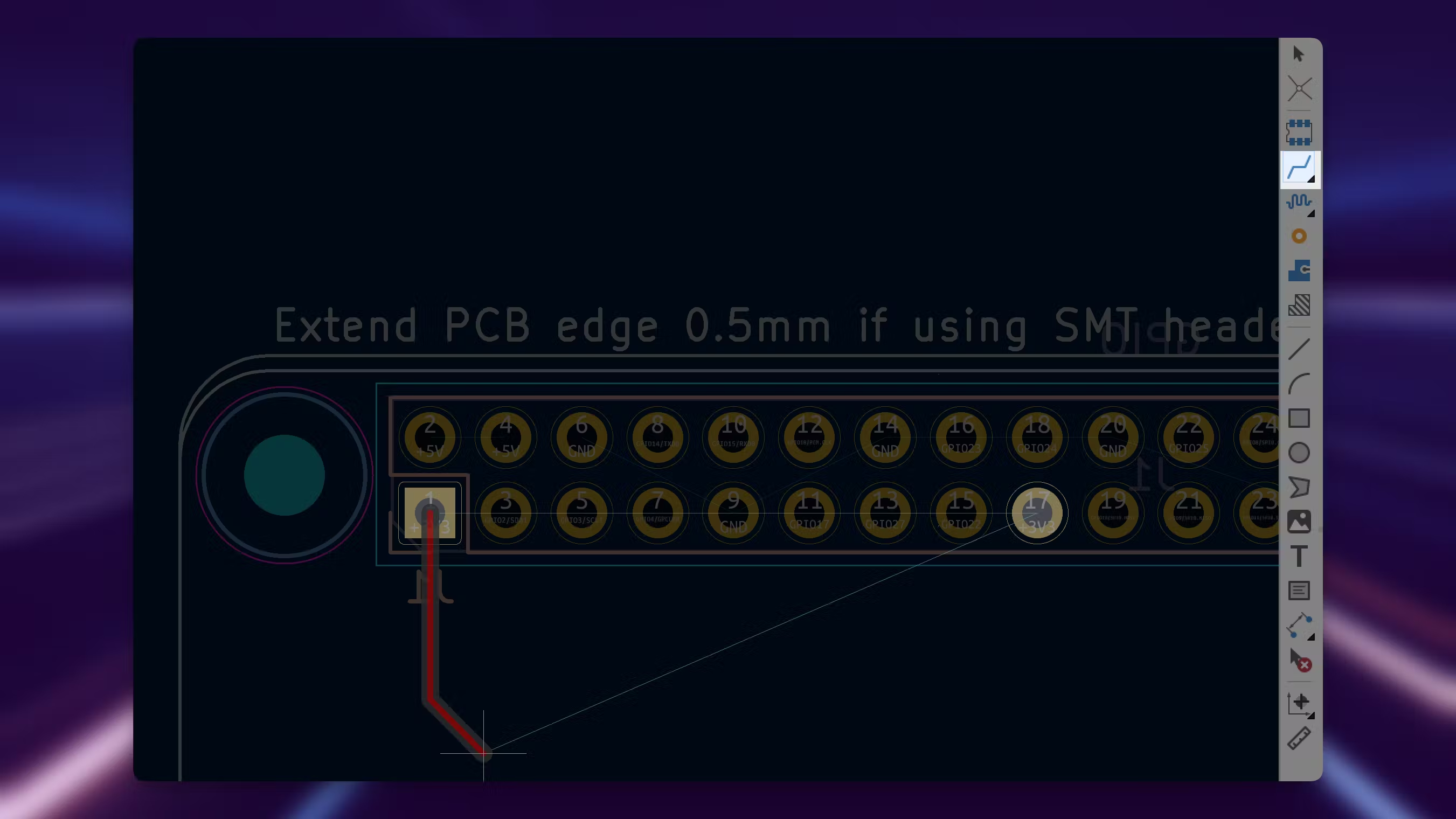
To start routing, click on a routing touch point and a trace will appear.
Press F to change the route angle (elbow) direction and W to change the size of traces.
Connect the components based on the schematic and airwires
As you route, you'll see air wires disappear and be replaced by copper. You can also switch the layer you're routing on by clicking V, to place a via and switch layers. After routing our board looks like so.
Real-time Design Rule Checks (DRC) guide you as you route, ensuring your design stays within manufacturing constraints.. Learn more.
Managing Ground and Power Planes
In KiCAD
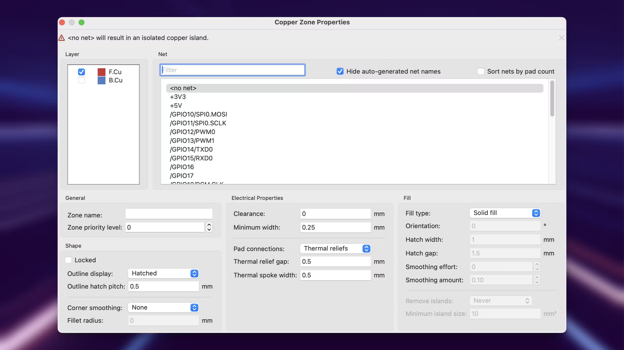
You manually create and configure copper pours for ground and power planes.
In Flux
Ground fills are managed automatically once a ground portal has been placed in the schematic. You can configure those fills to be tied to other nets. You can learn more about that here.
Automatic handling of ground and power planes reduces setup time and ensures consistency.