Getting Started in Flux: Schematic Design Guide
Before Watching
Make sure you've seen: Getting Started in Flux | Project Setup first!
Overview
In this tutorial, we'll be covering:
- Schematic Editor
- Flux's role in schematic design
- Community library
- Inspector Panel
- Building our first module
- Adding parts
- Wiring
- Net portals
- Flux review
- Design review
Schematic Editor
The schematic editor is where you build and simulate circuit schematics. Unique to Flux, everything you do here is synced in real-time to the cloud, which brings a number of benefits.
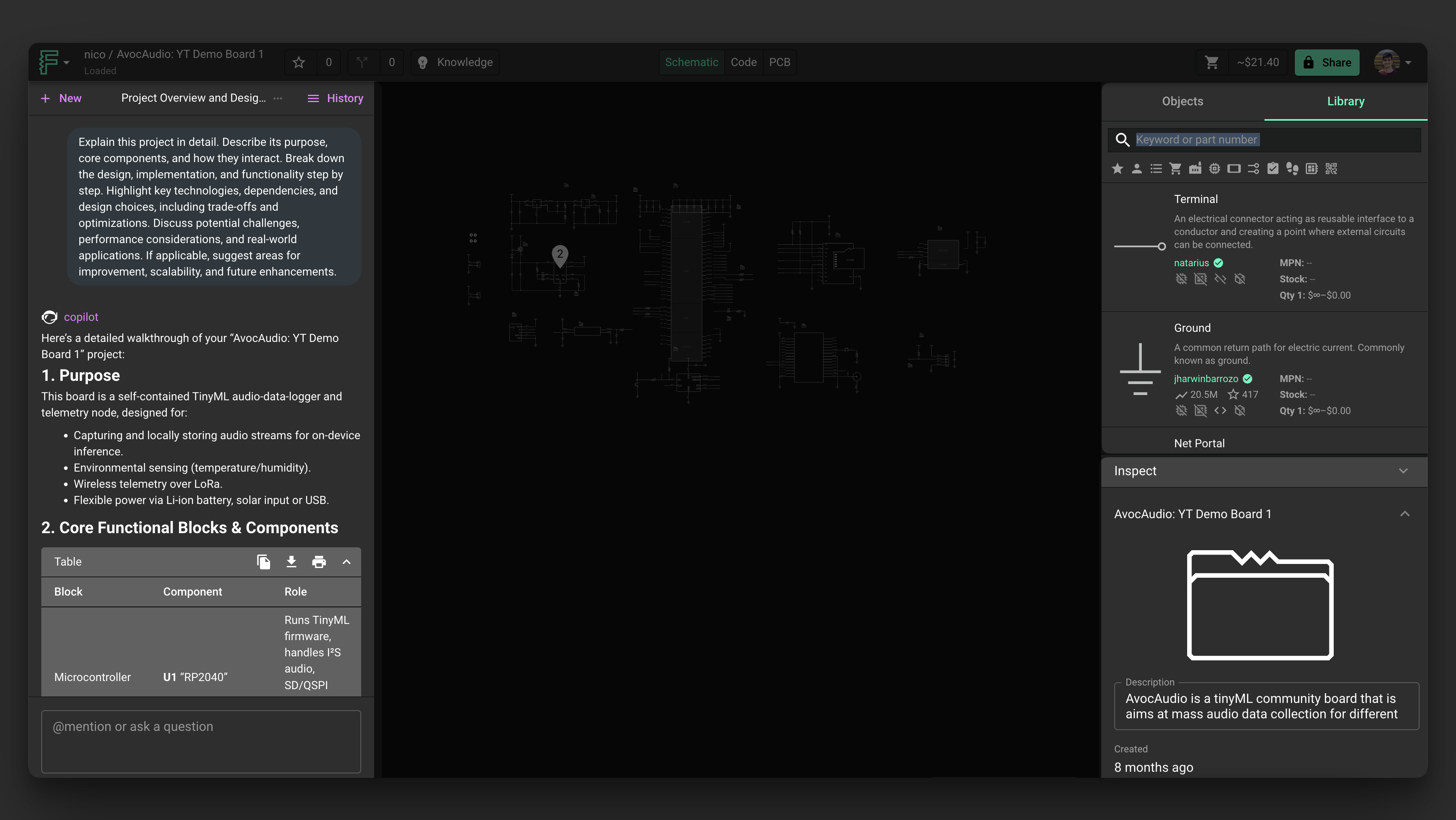
From left to right: Chat: use this interface to chat with Flux . - Library: list of all the parts you have access to Inspector: shows contextual information about the selected element (properties, pricing, etc)
Schematic with Flux AI
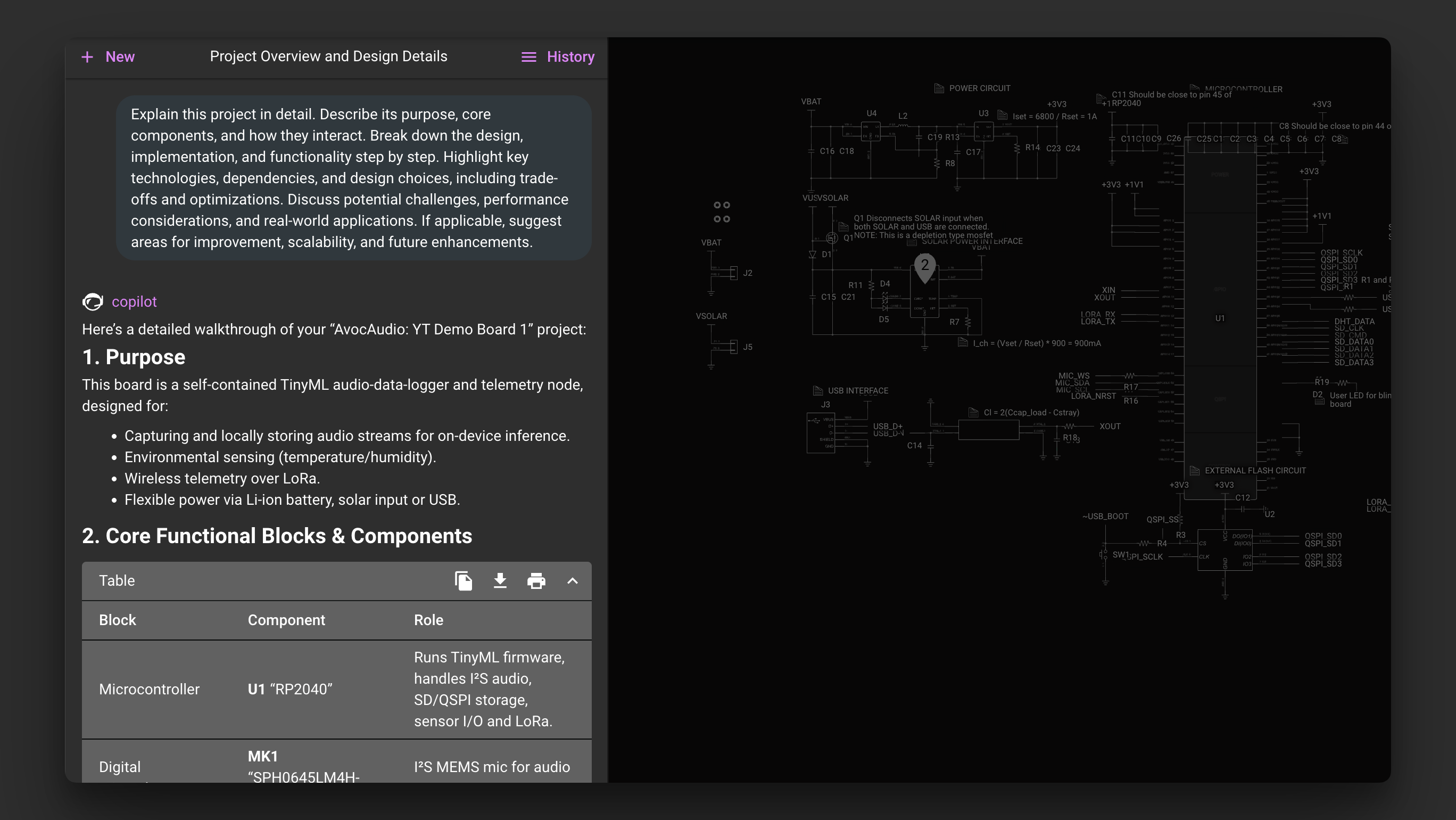
Flux is the industry's first AI-powered hardware design assistant integrated right into a PCB design tool. It is a custom-trained large language model (LLM) that understands your schematics, components, electrical connections, and bill of materials.
Flux understands the full context of your project, including your list of components, their connections, and related part datasheets. Because of this, Flux can help perform tasks such as part selection, part alternate evaluation, design feedback, cost-down analysis, and design optimization. Check out this document for a more comprehensive description of Flux and how to use it.
Community Library
In a previous section, we discussed how you can reuse existing projects. PCB designers have been creating symbols and footprints for the same parts and modules over and over again. The community library is where you'll find every available part and sub-layout that you and other designers have created.
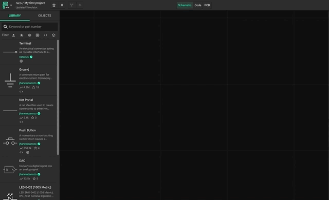
To do this, simply click and drag to add a part from the library into your schematics. You can use the search box to find the specific part or sub-layout you're looking for.
Inspector Panel
Use the inspector to view more information and change configurations for components, objects, and the project. It's located inside the Inspect tab in the right drawer, a unit on the right side of the editor.
It's contextual to your selection. When an object is selected, you'll see info about that object. If no object is selected (like if you click on an empty section of the canvas), the inspector will show information about the project. It's also contextual to the mode you're in. When you're on the Schematic, you see different information than when you're on the PCB. And when you resize its width, it can show even more information.
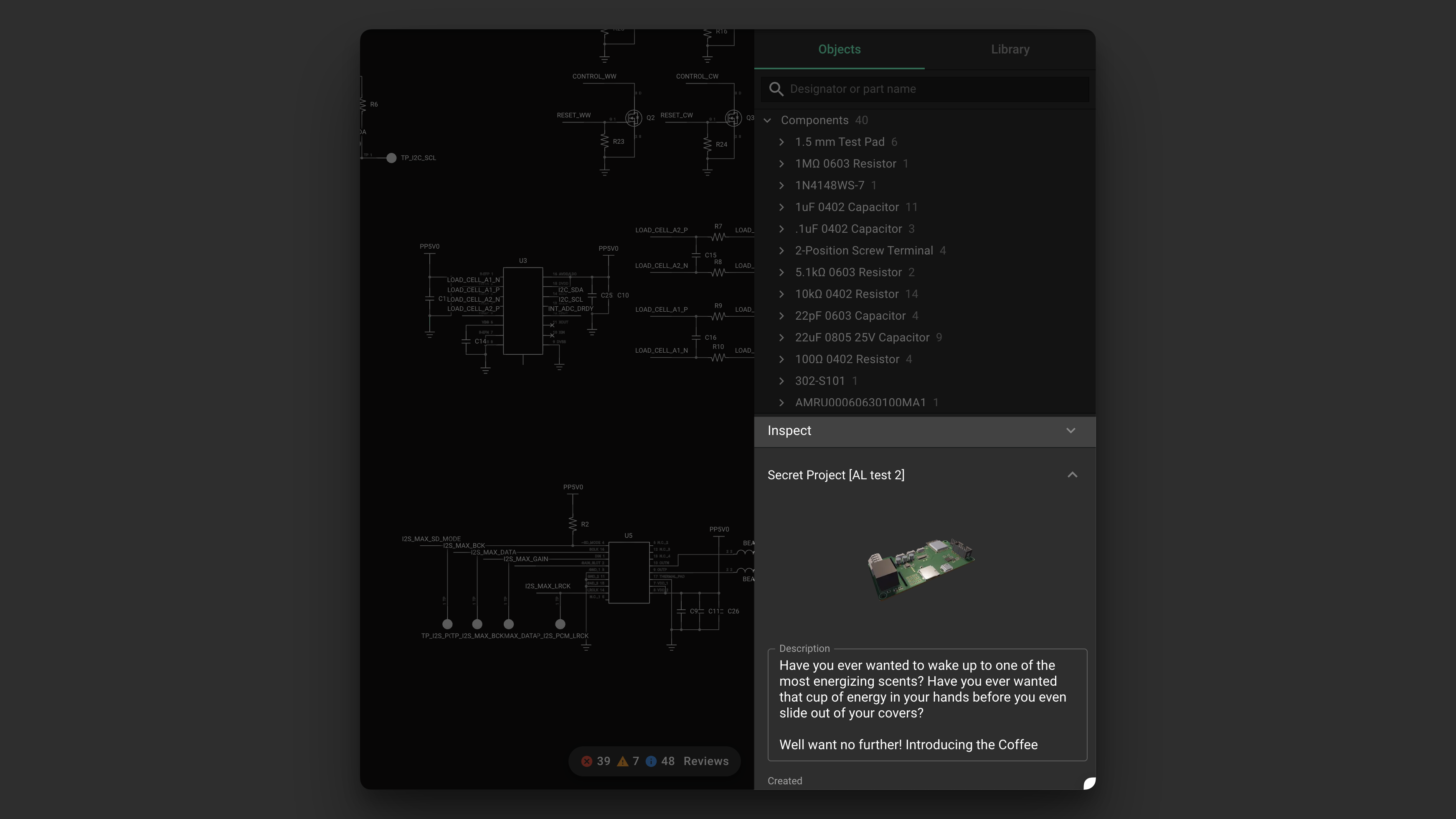
The inspector is located in the Inspect tab in the right drawer.
Jumping into Our Project
As a reminder, our main overall project goal is to modify a pre-existing ON-AIR board with:
- Intensity adjustment with slider by adjusting a feedback loop with a slider
- Push button for on and off
- USB-C power
- Powered by a single buck converter
- Feedback loop control using a slider
We'll start with creating the buck converter as a module. Buck converters are incredibly useful circuit blocks that allow for stepping down a voltage input. Since buck converters are used everywhere, creating a module for one will be useful in future projects, and in our own project's organization. Specifically, it will be contained in a module that will show it as a single symbol in the main schematic rather than all of its individual pieces, increasing readability.
Building our First Module
Modules can allow you to do 80% of the work in 30 seconds. In the case of our project, we will start with creating a digitally adjustable buck-converter with 0~1.9V output.
We'll start by building the module from parts, and then converting it so it can be reused. Then we'll be able to explain why this is so valuable.
How to Create a Module
Create a new project, and as long as it has a layout, it can be published as a module.
- Modules only interact with the outside world through terminals
- In creating a module, drag in your desired terminals —in other words, your inputs and outputs.
In our case:
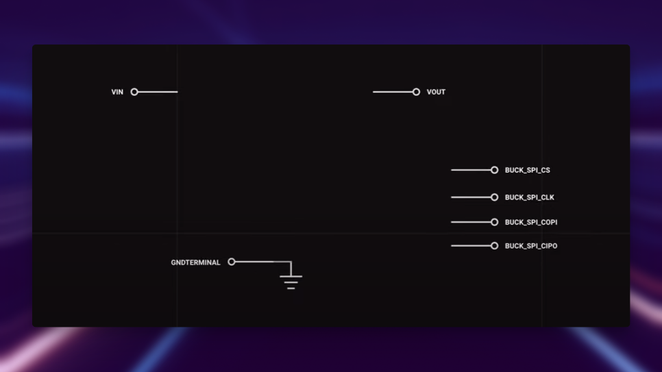
- Set input to VIn, output as Vout, in addition to SPI bus
- Module will be a controllable buck converter, so we will update the description to reflect that: 5V input to variable output controlled thru SPI interface
- Make sure you've also added ground terminal
- Then go ahead and publish it! As long as you've given the appropriate permissions, you should be able to access it in your library.
Accessing Preexisting Modules
Once we create our main project, we'll be able to drag in the module into it.
- To find them in the library, make sure they're published first (ctrl+p)
- To consume modules: you drag and drop them into your canvas
- Setting permissions to anyone can view sets it so that anyone can go into the library and find your module
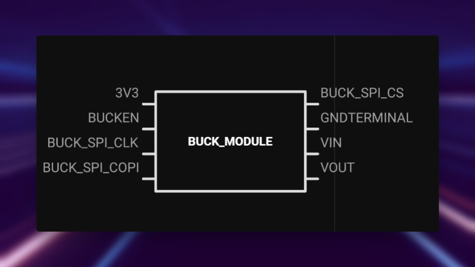
We now have our module framework with basic inputs and outputs. Simply double-click to edit it.
Adding a First Part into a Module
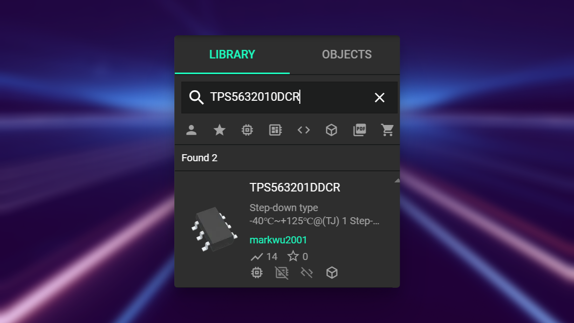
To add parts to a module, simply search for your desired parts in LCSE, then drag and drop from the library into the Canvas.
Many parts have the following details:
- Which user posted the part
- How many users it has
- Component Stock
- Etc.
You can add MPN to parts you know you'll be using later in your BoM. For generic parts such as the capacitor, you can familiarize yourself with common capacitor values and associated packages with good dielectric and voltage ratings.
Part Properties
For our first two parts, we want to add:
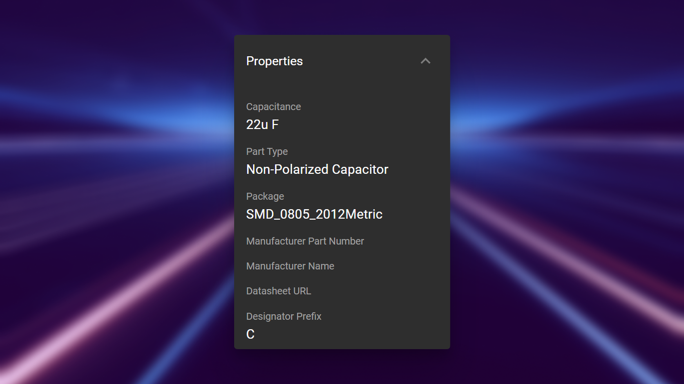
- A decoupling capacitor
- A TPS563201DDCR IC
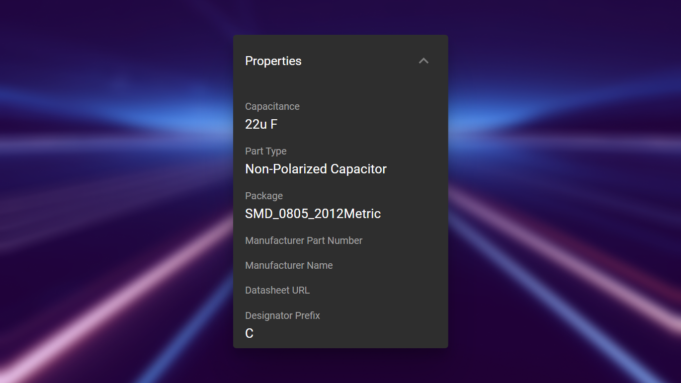
In Flux, we use properties to constrain our design. For example, some parts can change their footprint based on the package property properties (0603, 0805, etc.). Many built-in or user-created features may rely on these properties.
Aligning and Orienting Parts
You can drag parts around and utilize alignment markers between terminals.
Another method includes selecting multiple parts, right-clicking, and selecting in the align menu.
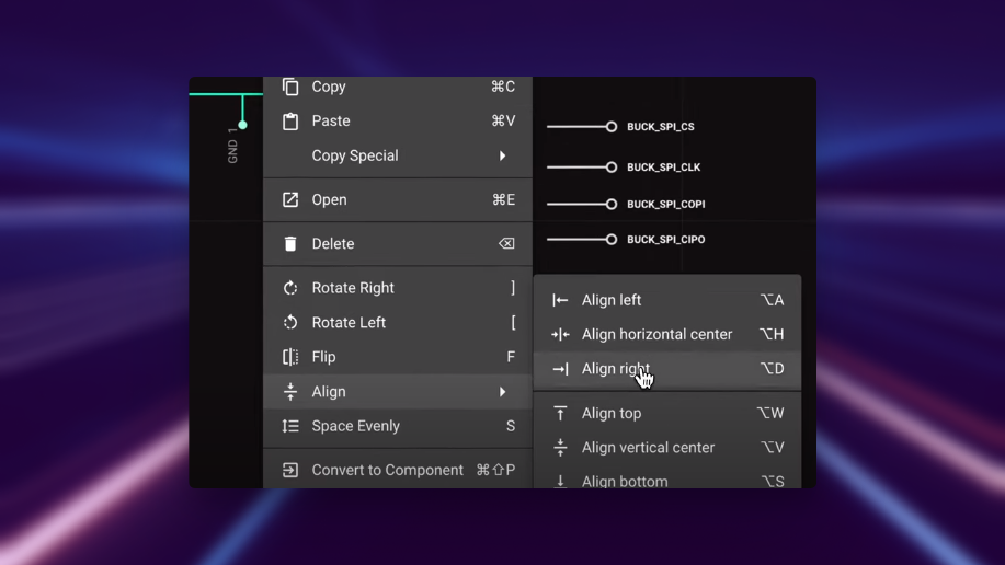
Additionally, you can select your parts, right click > align > 'align evenly', for a more aesthetic canvas. Furthermore, you can also use the shortcut s, or right click and "space evenly".
Placing Remaining Parts in the Module
We will now go ahead and place all the necessary remaining parts for the module.
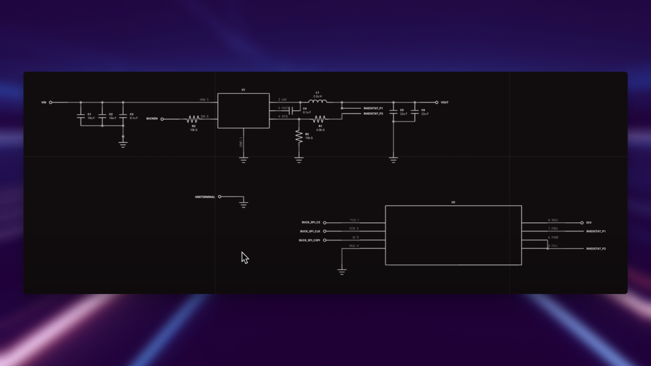
Connected to TPS563201DDCR
| Resistors | Capacitors | Inductors |
|---|---|---|
R1: 6.8 kΩ R2: 10 kΩ R3: 10 kΩ | C1: 10 uF C2: 10 uF C3: 0.1 uF C4: 0.1 uF C5: 22 uF C6: 22 uF | L1: 2.2 uH |
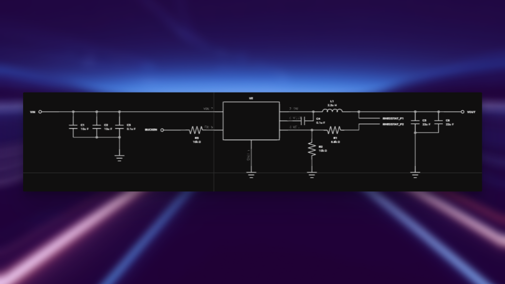
Connected to MCP41010T-I/SN
| Capacitors |
|---|
| C7: 0.1 uF |
| C8: 1uF |
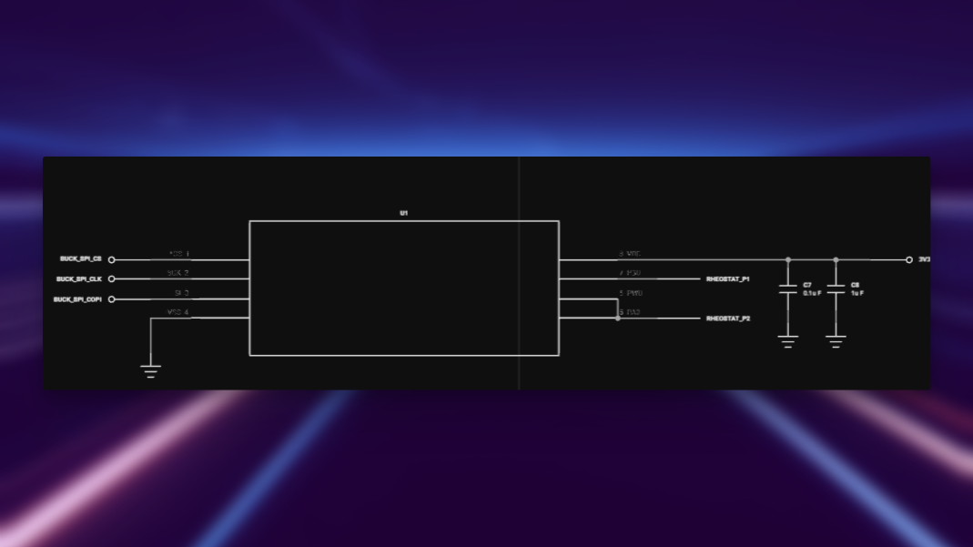
Along the way, we've noticed that we require additional inputs and outputs, more than those we already have. To do this, we simply added the relevant terminals with associated names. Below, we can see we've added a couple capacitors, a resistor, an inductor, and necessary grounds.
Wiring
To wire, simply hover over routing touch points, click, and begin routing.
- Press F to change the elbow direction
- Click on the screen to lock what you can see
- Click on another routing touch point to finish your connection
After wiring, our module schematic looks like so:
Net Portals
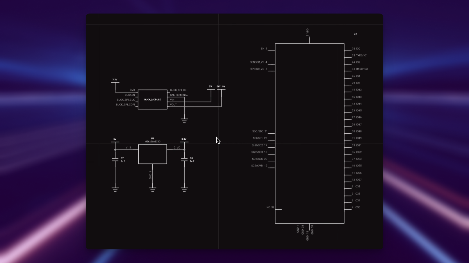
Net Portals (and power portals, there's no difference other than the visual symbol) are an alternate way to form electrical connections between terminals. Terminals connected to net portal labels of the same designators will be in the same net container in the PCB view. Here we've added power portals, such that all 5V-selected items will be connected to the PCB. Same goes for GND, 3.3V, and 0V~1.9V, and any other net portals we may want to add.
Updating and Publishing Modules
To publish a module to the library:
- Flux Menu > Publish changes
OR
- Ctrl + P
Remember to add notes so you don't forget the changes you've made! Now that our module is complete, we can go back to the top-level parent project.
The Value of Modules
The reuse of modules facilitates faster and more efficient project development as designers can leverage existing designs instead of creating everything from scratch.
- Modules differ from parts in that they comprise multiple elements.
- Modules can be shared and reused by others, fostering a community-driven approach to design.
- The concept of modules extends to nesting, allowing for the integration of multiple sub-layouts within a project.
Overall, modules offer a versatile, time-saving solution for designers looking to optimize their workflow and collaborate within a community.
Working in the Top-Level Project
After returning to the parent project, click on the pop-up menu to update your component across projects, found in the bottom left of the screen.
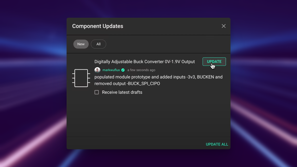
You can also check "receive latest drafts" so you don't need to keep manually updating it across revisions.
Adding Components to a Top-Level Design
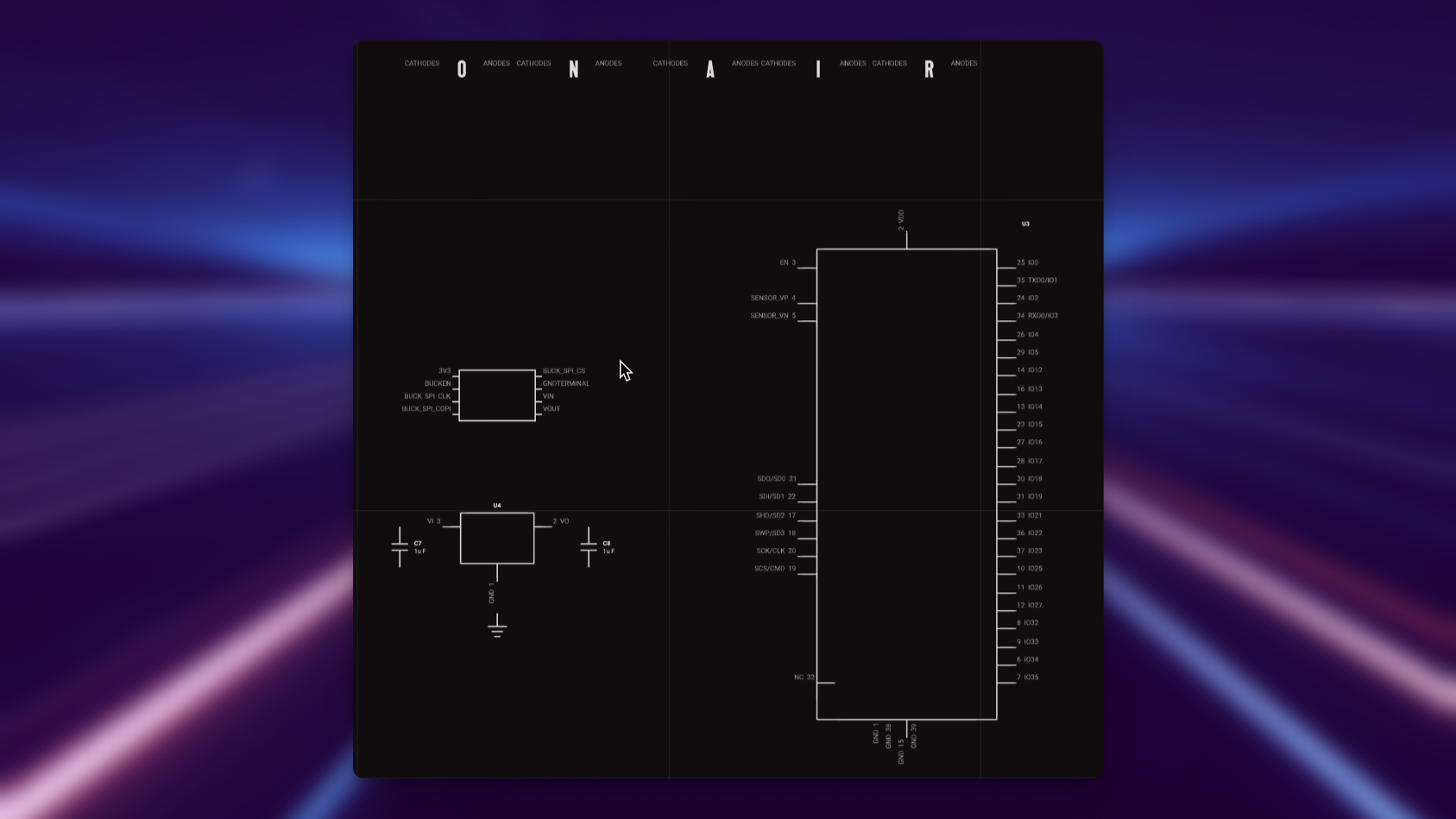
Now we add our additional components to the top-level design, as shown below.
Wiring Parts with Flux
We can use Flux (which uses net portals) to connect parts together:
- Select both parts by holding shift
- Right clicking
- Hovering over Flux
- Clicking connect-components
Alternatively, you can also ask this in a comment and press 'take action'
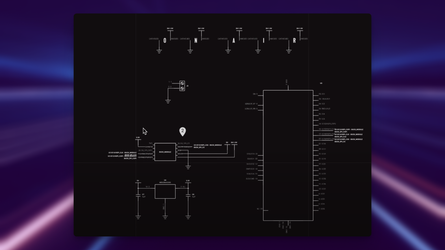
In this case, we've used Flux to connect the SPI bus from the buck module to the ESP32
Flux Design Review
You can ask Flux for a design review:
- In your canvas, right-click > Flux,
You'll have some options for reviewing your design, you can take the default prompt, edit it, and ask Flux for a design review.
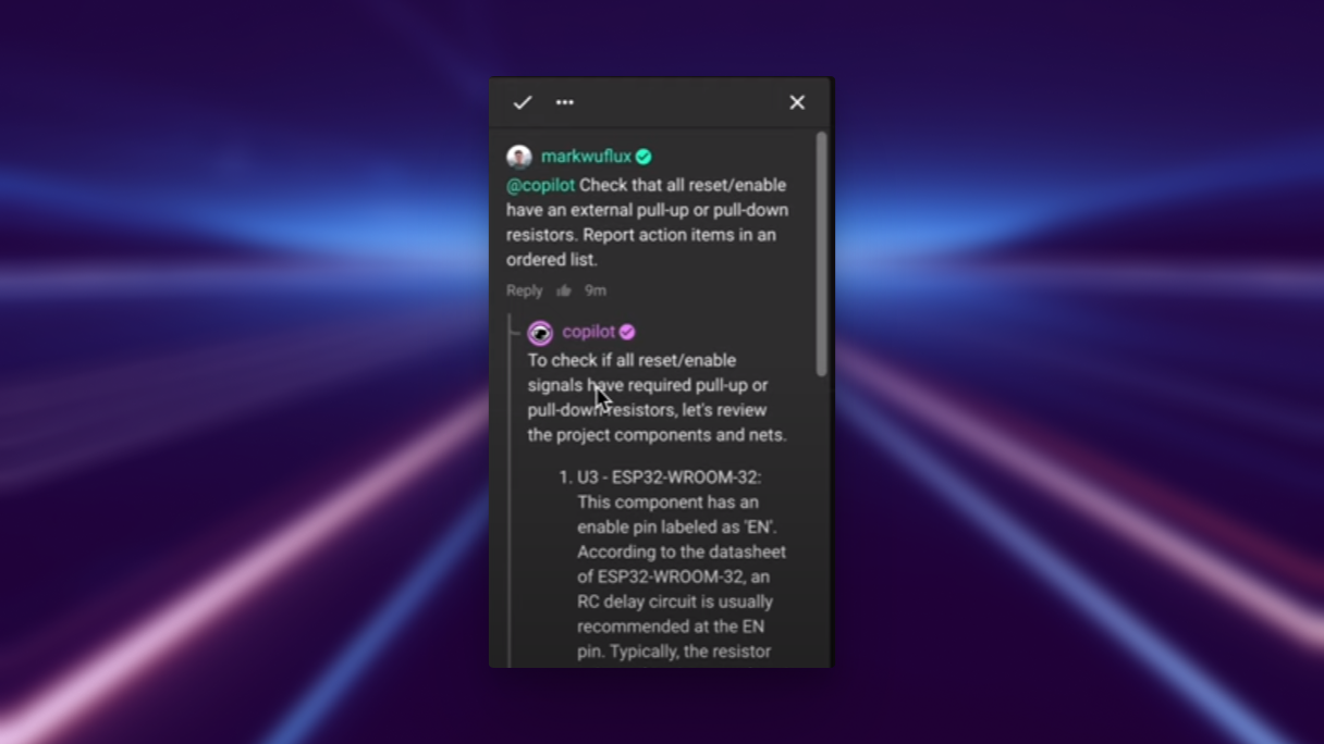
This acts as a good sanity check, but also can be vital for catching mistakes–and even providing some potential solutions and references for them. In this case, the enable pin was unconnected and required a 10k pullup resistor.
That completes our schematic! See below for a summary overview of the design.
Schematic Design Summary: an In-Depth Dive
The design is split up into a couple sections.
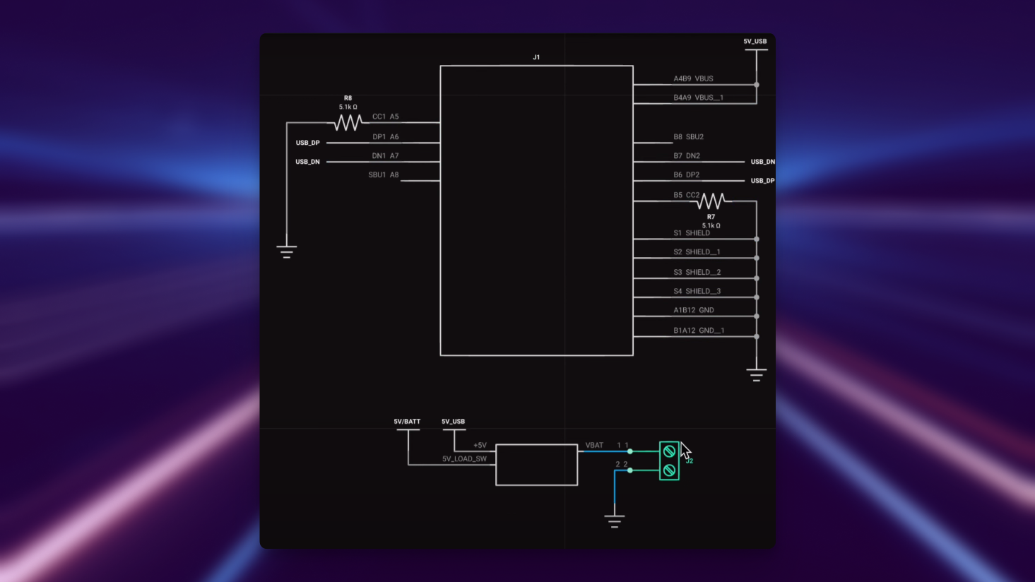
Power Input Section:
- USB-C and battery connection. The USB-C will get a regulated 5V with 500mA of input current if plugged into USB-C from the computer. Ideally, the user runs a 1A plug (which should be added as a note in the description)
- The two 5.1k resistors are used for power negotiation. If you used a USB-PD bring it to ensure 5V on the output.
- The 5V goes into a load switch that ensures if both a battery and a 5V power is supplied, then nothing explodes.
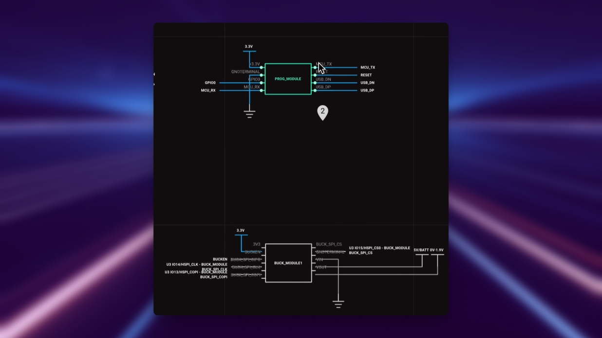
Below, we see the programming module which is a USB device that has serial and UART output with flow control. The flow control and GPIO0 are used for flashing the ESP32.
Troubleshooting Common Issues
Component Placement
- Alignment issues: If components aren't aligning properly, try using the alignment tools (right-click > Align) or keyboard shortcuts
- Component orientation: Use the bracket keys [ ] to rotate components if they're not oriented correctly
- Missing terminals: If you need additional inputs/outputs for your module, add them before wiring to avoid having to rewire connections
Wiring Problems
- Connection not forming: Ensure you're clicking directly on the routing touch points (small dots on pins)
- Elbow direction: If the wire isn't bending as expected, press F to change the elbow direction
- Net portal connections: Verify that net portals have exactly the same designator to ensure proper connection
Module Management
- Module not appearing in library: Check that you've published the module (Ctrl+P) and set appropriate permissions
- Changes not propagating: If updates to a module aren't appearing in the parent project, check for the update notification in the bottom left or manually update
- Module editing: If you can't edit a module, ensure you're double-clicking to enter edit mode
What's Next
Now that you've completed the schematic design, you're ready to move on to:
- PCB Layout and Routing - Learn how to place components and route traces
- Export and Manufacturing - Prepare your design for production
- Layout Rules Deep Dive - Master Flux's powerful layout rules system
- Using Modules - Explore more ways to create and use reusable modules
- Flux Deep Dive - Discover more ways to leverage AI in your design process