Modules allow you to reuse layout sections and drop in fully functional blocks into your design.
Overview
A module is a block containing a complete design section, including parts, traces, vias, etc. These blocks can then be placed into existing projects to reuse previous designs with minimal effort.
This idea of PCB layout reuse is a great way to help designers build things faster. If you wanted, you could go back into your library of PCB projects, mix and match the modules you need in a new project, and arrange it all in a new PCB.
Modules vs. Parts
Understanding the difference between these two concepts is crucial. Here's a brief description of each:
- Parts represent single elements in the bill of materials, for example, resistors, connectors, etc. In Flux, you can identify a part because its schematic only contains terminals.
- Modules will appear as multiple elements in your bill of materials. As modules can contain multiple parts, each will appear as a new line in your BoM. You can distinguish a module because its schematic includes parts, wires, and terminals.
Modules vs. Projects
What then distinguishes a module from a project?
The primary difference is that a module is any project that has been published to the library. Essentially, any project can be transformed into a module simply by publishing it to the library and, therefore, able to be included in another project (hence the name module).
Hierarchical Design
Flux doesn’t use traditional schematic sheets. Instead, hierarchical design is achieved through modules. Each module is a self-contained block that can include everything from parts and nets to traces and vias. You can drop these into any project to reuse full design sections. It’s like having a library of ready-made building blocks—perfect for remixing old projects or speeding up new ones without starting from scratch.
Working with Modules
Connecting to Internal Module Nets in a Larger Project
Let's now explore what happens when you incorporate a module into another project. We will refer to the latter as the "host project".
Nets within the module are entirely separate from nets in the host project. The only method to connect to a net from the module is through a terminal.
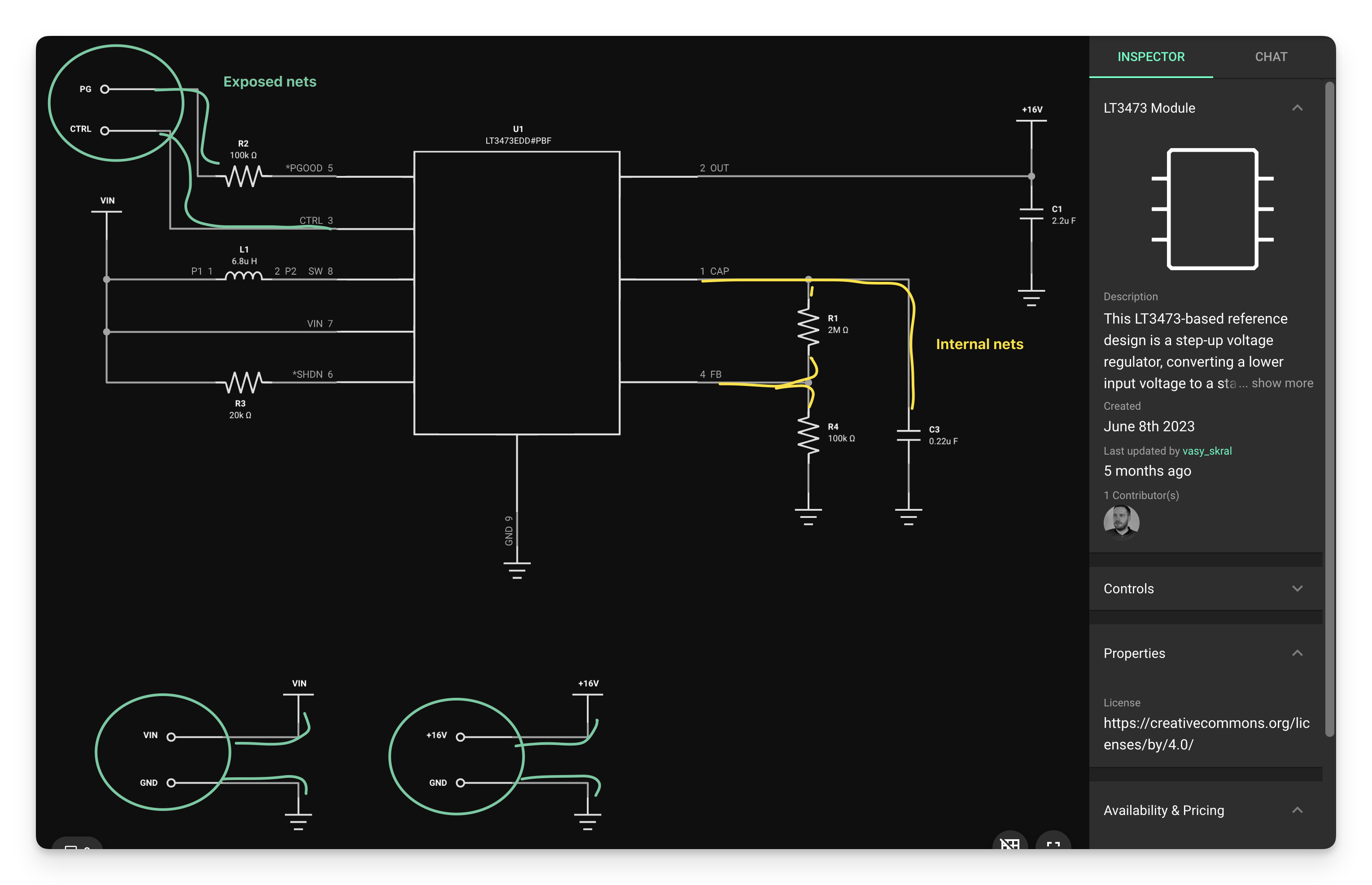
Internal nets from a module (shown in green) can be exported to be used in the host project by connecting a terminal

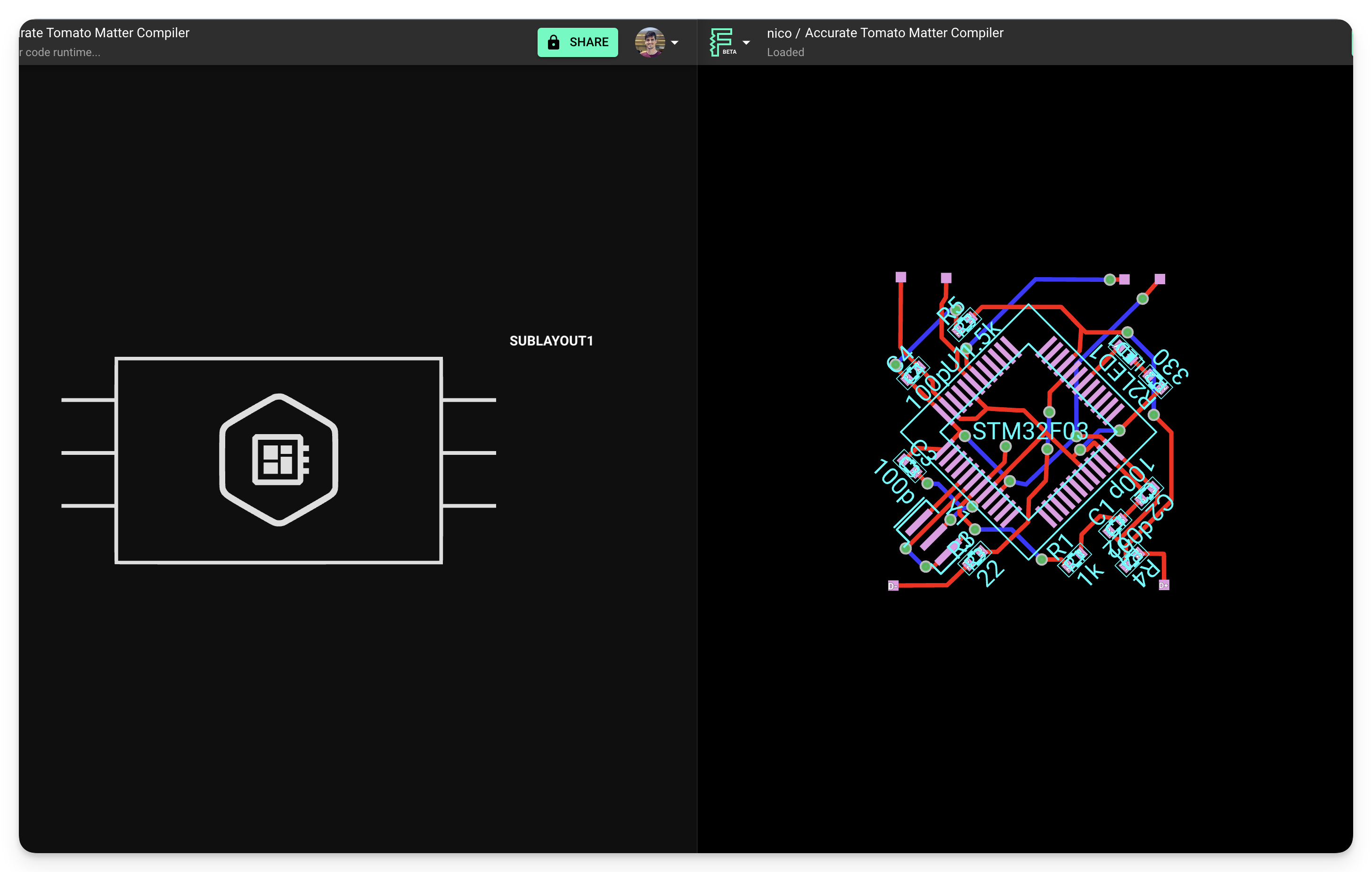
Exposed nets show up as pins on the module symbol in the host project. Each terminal in the module corresponds to a pin in the symbol.
Designator Renaming
When a module is added to your project, the designators within it are automatically renamed if there are any conflicts. This is known as "designator mapping."
For example, a module containing resistor "R1" will be mapped to "R2" if there already exists a resistor "R1" in your project.
This ensures that your BoM contains unique designators for each part.
How does "designator mapping" work?
Designator mapping only happens to a module's parts when it is added to your project, or when its version is updated. It does not affect other parts in your project.
- When a module is updated to a new version, any previous mapping of its parts is left untouched. This ensures existing designators are as kept as stable as possible.
When renaming parts, the "Designator Prefix" property is used to determine the next available designator.
Designator-based selectors will still work after then mapping is applied.
- For example, if a rule targets #R1 in a module, then the module is imported and R1 becomes R2, the rule still applies to that element.
- This is true for multiple levels of remapping (i.e. modules within modules).
Net Renaming
When placed in a host project, internal nets of a module will be renamed to avoid unintentional name clashes. All nets in the module will remain disconnected from the host project unless they are exposed via a terminal and connected within the host project.
This principle also applies to ground nets. Ground-connected nets within a module will not link to the ground in the host project unless the net is exposed through a terminal and connected to ground in the host project. Consider these two examples:
Example 1
In this module, there is an internal net connected to ground, but not exposed through a terminal. The host project has another ground-connected net.
The two nets are connected to a ground symbol, one inside the module, and one in the host project. But since they're not connected to each other, we can see in the PCB layout, that the two grounds are disconnected from each other.
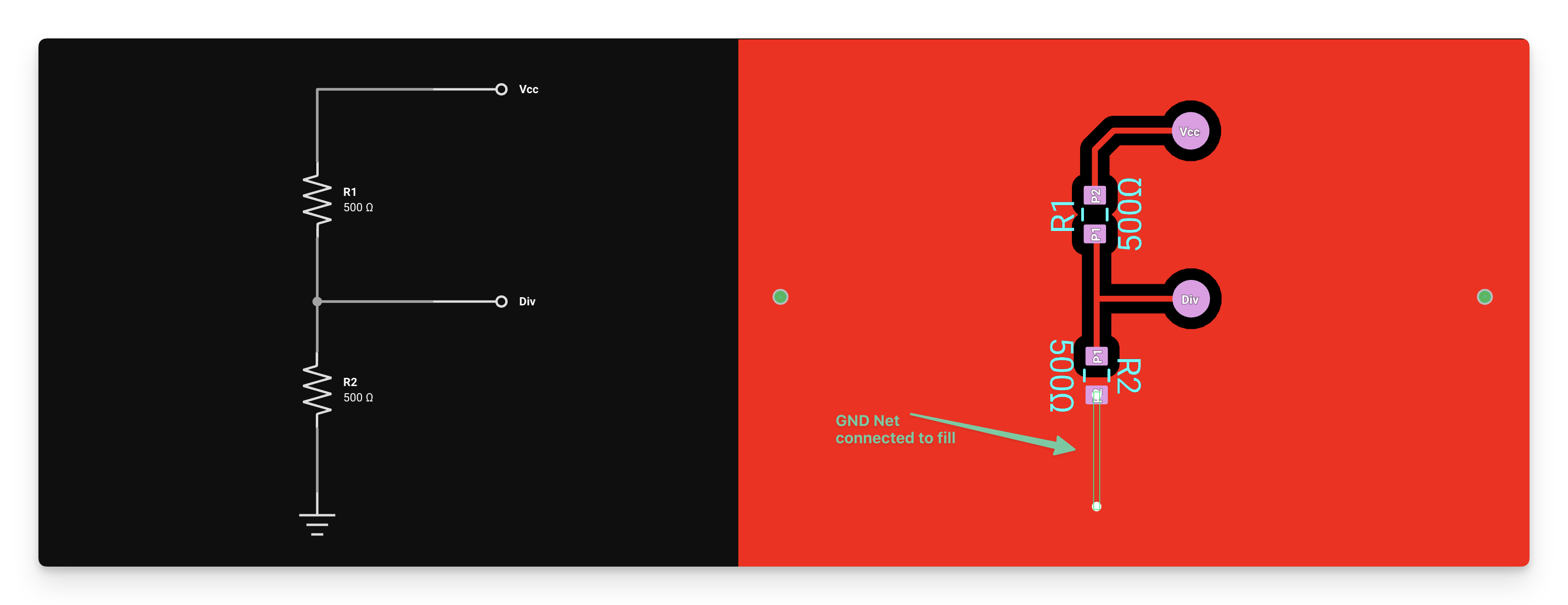
Module's net is connected to ground and the ground fill.
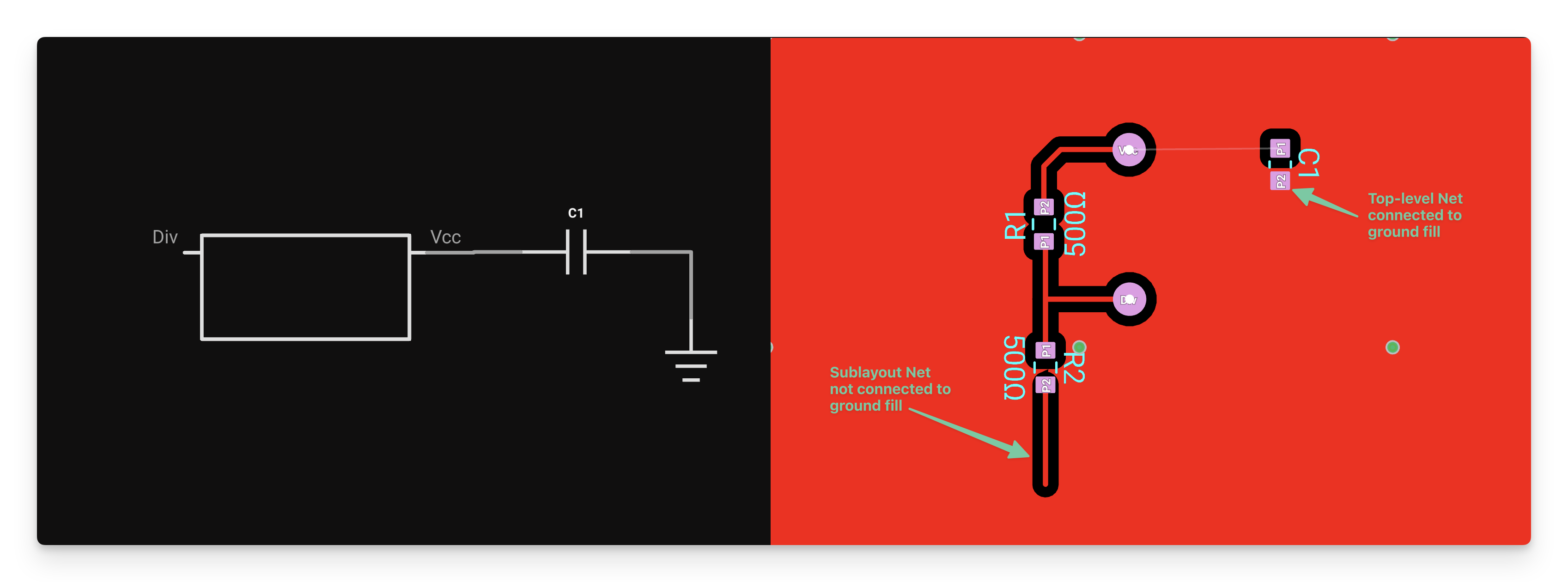
Module's ground net is not connected to ground (or the ground fill) in the host project.
Example 2
We're using the same module from Example 1, but in this case, we're exposing the module's ground net via a terminal, and connecting it to ground on the host project. See that both traces or now connected to each other and to the ground fill.

Module net is connected to ground, and the ground fill. It is also exposed through a terminal.
Nesting Modules
There's really no limit to the number of modules you can connect together in a project. The same idea applies to nesting: you can nest modules within modules up to any depth, something which isn't possible in standard ECAD applications.
A great example of a project that uses nested modules is the STM32-Modular project. This project contains two resonator modules that give a good concept example.
A Community Approach
A fantastic feature of Flux is the ability to share parts and modules publicly. Users can find and integrate publicly shared layouts from other users, just like you would with publicly available parts. The platform also contains GitHub-like version control features that allow forking, as well as a public library that helps users quickly get started creating new designs.
Benefits of Using Modules
Using modules in your PCB designs offers several advantages:
- Time Savings: Reuse proven designs instead of recreating them from scratch
- Consistency: Ensure the same design standards across multiple projects
- Reliability: Use tested and verified circuit blocks
- Collaboration: Share and use modules created by other team members or the community
- Maintainability: Update a module once and apply changes across multiple projects
Troubleshooting Common Issues
Module Integration Problems
If you're having trouble integrating a module into your project:
- Verify that the module has been properly published to the library
- Check that all necessary terminals are exposed for connections
- Ensure you have the correct version of the module
Connection Issues
If connections between modules and the host project aren't working:
- Verify that terminals are properly connected to the nets you want to expose
- Check that connections in the host project are properly made to the module pins
- Remember that internal module nets are isolated unless explicitly connected
Designator Conflicts
If you're experiencing issues with designator mapping:
- Check for any custom designator rules that might be interfering
- Verify that designator prefixes are consistent
- Consider manually renaming critical components if automatic mapping isn't sufficient
What's Next
Now that you understand what modules are and how they work in Flux, you might want to explore:
- How to Use a Module - Learn best practices for incorporating modules in your designs
- How to Create a Module - Discover how to create your own reusable modules
- Publishing a Part to the Library - Learn how to share your modules with others
- Version Control Deep Dive - Understand how to track changes to your modules over time