Learn how to approach a module design to get the most value out of them.
Overview
Although you can create a module with any arrangement of components, some up-front planning will help you be more efficient and make reusing designs easier. This tutorial covers some of the best practices for using modules.
Single-Sided vs. Double-Sided Placement
Module in Flux can be designed with components on a single or multi-sided board. Placement on both sides of the board could limit your ability to place other components, including components that might need to connect to the module. Inside the PCB Editor window in Flux, a module can be flipped to the opposite layer with the same command that is used for any other component.
There are some advantages to making all of your modules single-sided:
- You can place two single-sided modules in the same area on opposite sides of the board
- Placement on only one side leaves a lot of space for routing on the back layer
However, for some designs, placement on both sides might be the best way to create a more compact layout. Make sure to consider both options when designing and placing components in a module.
Place Terminal Pads Around the Edge
Generally, pins on integrated circuits are laid out near the edge of the package, making them easily accessible. This placement strategy is also preferable in designing modules.
Putting connections around the edges of the module makes them more accessible to other circuits.
Let's consider what happens if a module designer doesn't follow that guideline in the example is shown below:
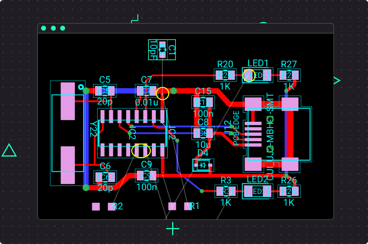
In the design above, we've placed a module in a project with 3 extra components (R1, R2, and C1). The module designer has placed pads (marked in yellow) in the inside of the module. This would require the use of vias to access pads or place components in the bottom layer. This is not ideal because we might be interfering with the module design.
Create Module Based on Function
A great way to build modules is to build circuits that perform specific functions. If you look through the public library in Flux, you’ll see many examples of modules, with a variety of functions. Some examples of functionally-specific modules include:
- Power regulator circuit, either with discretes or a controller
- USB controller and connector
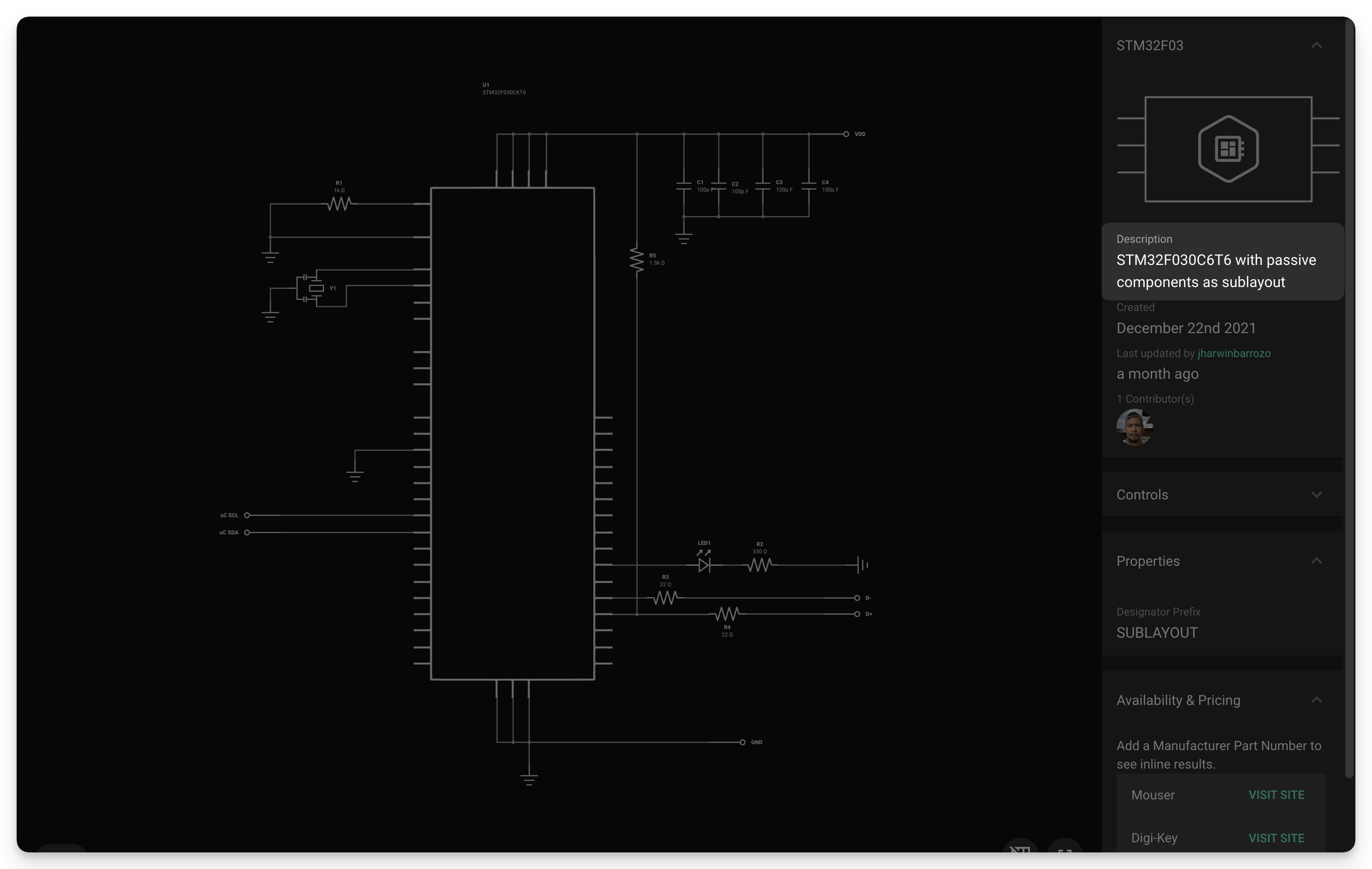
- Microcontroller with its decoupling capacitors
- Interface bridge circuits
- ADC or DAC with passives for configuration
- Op-amp circuits with specific gain and feedback design
If you focus on creating modules based on function, it will be much easier to combine your modules later.
Expose Every Interface
If you’re creating a module for a component like a microcontroller or an ASIC, it’s a good idea to expose all the interfaces available in the IC so they can be accessed through the module. This means adding terminals to every interface on the microcontroller (like UART, SPI, etc.) even if you don't expect to use them in your current design.
Doing so will require more effort upfront, but it will make your module more reusable, saving you time in the future.
Write a Clear Description
Make sure your module has a concise description of its functions, what other components might be needed, what power level is necessary, and any further details needed to make the circuitry work correctly. Your future self will thank you when using your module in a future project.
This is also particularly important if you're planning to make your module public. Having a clear description will help other Flux users know if that module is right for them and how to use it.
In summary, think of modules as building blocks for reducing your design effort if used properly. You can link them together however you want in the schematic without changing their internal placement and routing.