
Get solid ground planes and power planes without drawing them by hand.
Configure ground fills and power fills (ground planes and power planes).
Overview
There are a few general guidelines to remember about using copper fills in Flux:
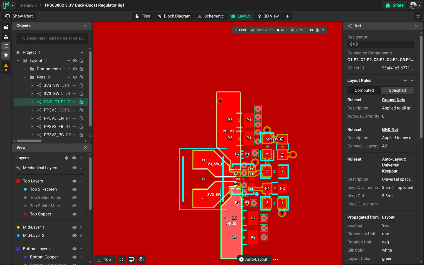
All copper fills (ground and power) are hidden by default. Here's how to make them visible.
Ground fills are enabled in every layer by default. Here's how to disable them.
Power fills are disabled in every layer by default. Here's how to enable them.
Stitching vias are not applied automatically. Here's how to configure them.
Turn imported copper fills into live pours
Ask Flux to replace imported fixed copper fills with editable Flux pours.
Flux converts imported fill pieces into dynamic pours on the copper layers connected by the net's vias. It turns off the imported fill pieces and stitching vias for each converted net. If two nets share a copper layer, Flux asks which net should pour on that layer before it changes it.
After the conversion, Flux reports the source and current state of each copper layer. Review the per-layer results in the chat.
Enable/Disable Copper Fills
Ask Flux to enable or disable a copper fill on the layers that you name.
To do it in the editor:
Fills can be enabled or disabled on each layer by assigning a "Connected Layers" rule to the target net. If the target net is a ground net it is known as a ground fill, while if the target net is a power net it's known as a power fill.
To enable or disable a copper fill for a target net:
Select the target net (nested under Root → Layout → Nets in the Objects panel
Add a "Connected Layers" rule from the "object-specific rules" menu on the right.
Select all layers for which you want the fill to be enabled. Leaving the text box empty will disable the fill connected to that net on every layer.
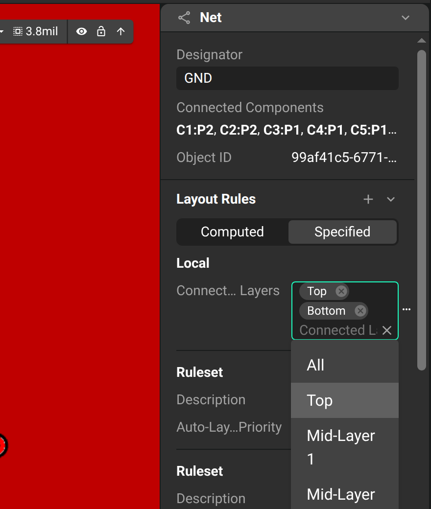
Leaving the "Connected Layers" rule empty will disable copper fills on every layer for that net.
Ground fill layers are not defined as negative layers in the Gerber files; they will appear as standard positive layers once the PCB is exported to Gerber files.
Ground fills on the GND net
Ask Flux to configure a ground fill on the GND net and name the board layers to connect. Pads on the GND net connect to the fill according to the net's Connected Layers rule.
Select the GND net, then set Connected Layers in the rule editor. See Enable/Disable Copper Fills.

Copper Fills Visibility
When fills are enabled, their visibility can be toggled within the Layer panel in the PCB editor. As shown below, there is an option to disable only the fill visibility next to the layer visibility tool.
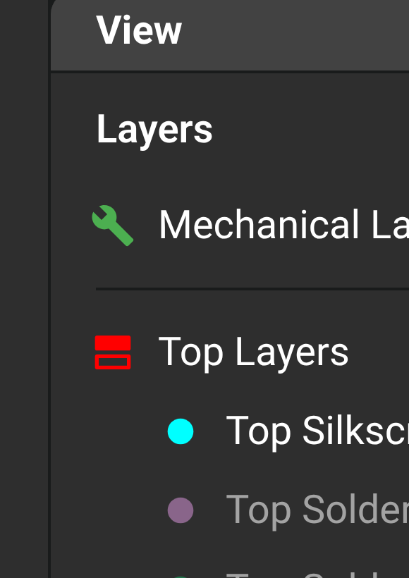
Note: toggling the visibility button will not disable the fill, it will only hide it from the view. Removing the fill altogether can only be done through the "Connected layers" rule.
Via Stitching
Ask Flux to add via stitching to a fill.
To do it in the editor:
Via stitching can be enabled and configured with the use of two rules:
Fill Stitching Density: vias will be spaced by the amount specified in this rule. Any non-zero value enables via stitching.
Fill Stitching Offset: shifts the via stitching block by the amount specified.
Follow these steps to add one or both of the rules:
Select the ground net (nested under Layout → Nets → GND in the Objects panel)
Add the desired rule from the "object-specific rules" menu on the right.
Enter the offset and/or density values as distances.
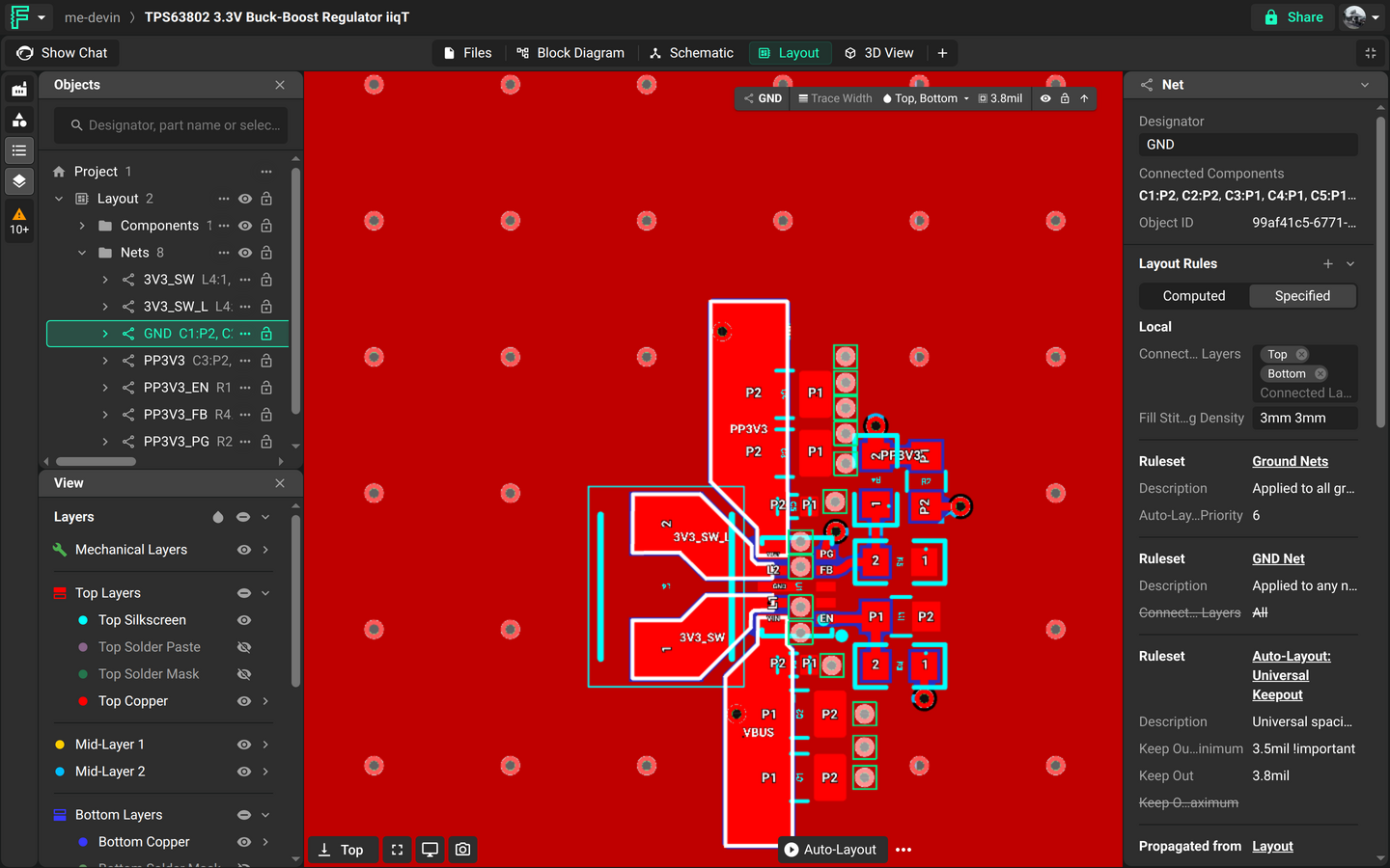
Note: both rules accept x and y input (vector rules). For example, typing "10mm 13mm" on Fill Density will create stitching with 10mm separation on the x-axis and 13mm separation on the y-axis.
Copper Islands Removal
Copper Islands are defined as pieces of copper in a fill that are not directly connected to a pad or via. To minimize the removal of copper, Flux's island removal algorithm is designed to automatically insert vias (referred to as "Island Vias") where possible.
Flux classifies pieces of copper as islands when they lack a direct connection or a via connection to the target net, then removes them.
Island Vias
The algorithm analyzes fill geometry to determine which pieces of copper can be connected to the net that the fill belongs to through an Island Via. It can keep islands connected through multi-layer routes to the target net. You do not need to create a path for the island vias. The process works according to the following specifications:
Island Vias are dynamically adjusted. Meaning that whenever there is a change in the layout due to the addition or removal of a pad, or the creation or removal of a trace, the algorithm will recalculate connections and decide if an Island Via is necessary or possible.
Island Vias are always through vias. Meaning they will only be inserted where a fill connected to the same net already exists on every layer both below and above.
Island Vias respect minimum trace widths. Meaning they will not be inserted if the insertion of the Island Via would breach the minimum trace width on any layer.
Island Vias will only be connected to fills. Meaning they will not be inserted on top of vias, pads, traces, or any other elements apart from fills.