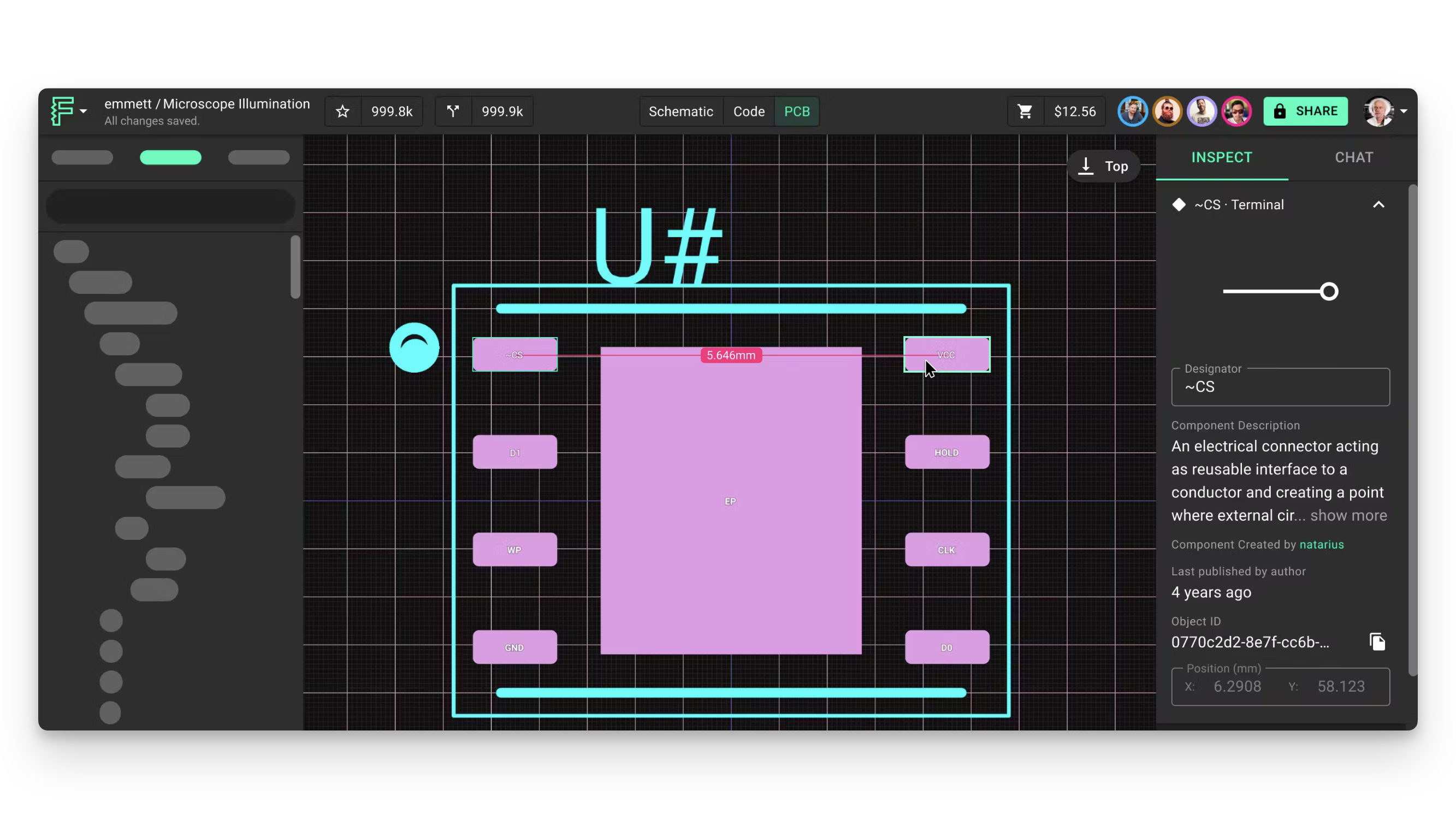
Measuring Distances in PCB Design with Flux
Streamline your workflow with quick and precise validations using Flux's intuitive automatic and manual measurement tools.

Overview
Accurate measurements are essential for successful PCB design, ensuring components fit correctly and manufacturing requirements are met. Flux provides both automatic and manual measurement tools to help you validate your designs quickly and precisely.
Automatic Measurement
Flux's automatic measurement system displays distances in real-time as you work, making it easy to verify spacing without interrupting your design flow.
How Automatic Measurements Work
Measurement lines and text appear automatically on the canvas when you select an object and hover over another object:
- By default, measurements display in a straight line between the closest points
- The units are inherited from the selected object
- Hovering near the edge of an element results in edge-to-edge measurements
- Hovering near the center shows center-to-center measurements
Customizing Automatic Measurements
Use these keyboard shortcuts to customize how measurements are displayed:
| Action | Shortcut |
|---|---|
| Display measurements on X and Y axes | Hold ⇧ (Shift) |
| Measure elements within components | Hold ⌘ (Command) on Mac, or CTRL on Windows |
| Combine axis and component measurements | Hold ⇧ + ⌘ (or ⇧ + CTRL) |
| Toggle automatic measurements on/off | Press ⇧ + M |
Manual Measurement
For more deliberate measurements, use the manual measurement tool to precisely measure the distance between any two points on your PCB.
Using the Manual Measurement Tool
- Select the empty canvas (click on any area without components)
- Right-click and select "Measure Distance (M)" from the context menu
- Click on the first point you want to measure from
- Click on the second point to complete the measurement
- The distance will be displayed in millimeters (mm)
Keyboard Shortcut
- Create a manual measurement: Press M while the canvas is selected
Best Practices for Accurate Measurements
- Use edge snapping: When measuring between components, click precisely on edges for accurate results
- Verify critical clearances: Double-check minimum clearances between high-voltage traces or components
- Measure at multiple points: For irregular shapes, take measurements at several points
- Use X/Y axis measurements: Hold Shift for separate horizontal and vertical measurements when checking alignment
Practical Applications
- Component clearance verification: Ensure components have sufficient spacing for assembly
- Trace width validation: Verify trace widths meet current-carrying requirements
- Manufacturing constraint checks: Confirm your design meets fabrication house specifications
- Thermal management: Measure distances between heat-generating components
Troubleshooting Common Issues
Inconsistent Measurements
- Issue: Measurements seem inconsistent or inaccurate
- Solution: Ensure you're clicking precisely on component edges and check your grid settings
Measurement Tool Not Responding
- Issue: Manual measurement tool doesn't activate when pressing M
- Solution: Make sure you've selected the empty canvas first, not a component
Units Display Problems
- Issue: Measurements display in unexpected units
- Solution: Check the units setting in your project preferences
What's Next
Now that you understand how to use Flux's measurement tools, you might want to explore:
- Design Rule Checks - Learn how to automatically verify design constraints
- PCB Rules Reference - Understand how to set up rules for consistent spacing
- Component Placement Guide - Master techniques for optimal component placement
- Manufacturing Preparation - Prepare your design for fabrication