Create your own modules for circuit blocks to easily reuse in any project.
Overview
The process of creating a module is similar to the one used to create a regular PCB layout but with some additional differences. In this tutorial, we'll show you how to create a module and best practices to get the most out of your module.
How To Create a Module
The main difference between a standard PCB layout and a module is the presence of terminals. While terminals are optional for standard designs, they are required for a module to work. This is because the terminals are used to connect the module to other components once the module is placed in a project.
The process to create a module is as follows:
- Create the circuit you want to make a module out of
- Add terminals to establish the connections
- Connect the terminals' pads in the PCB editor
- Add a designator prefix
- Publish the module
1- Create a circuit
Create the circuit you want to convert into a module. Make sure you follow some of these Module Design Best Practices to get the most out of your design.
2- Add terminals
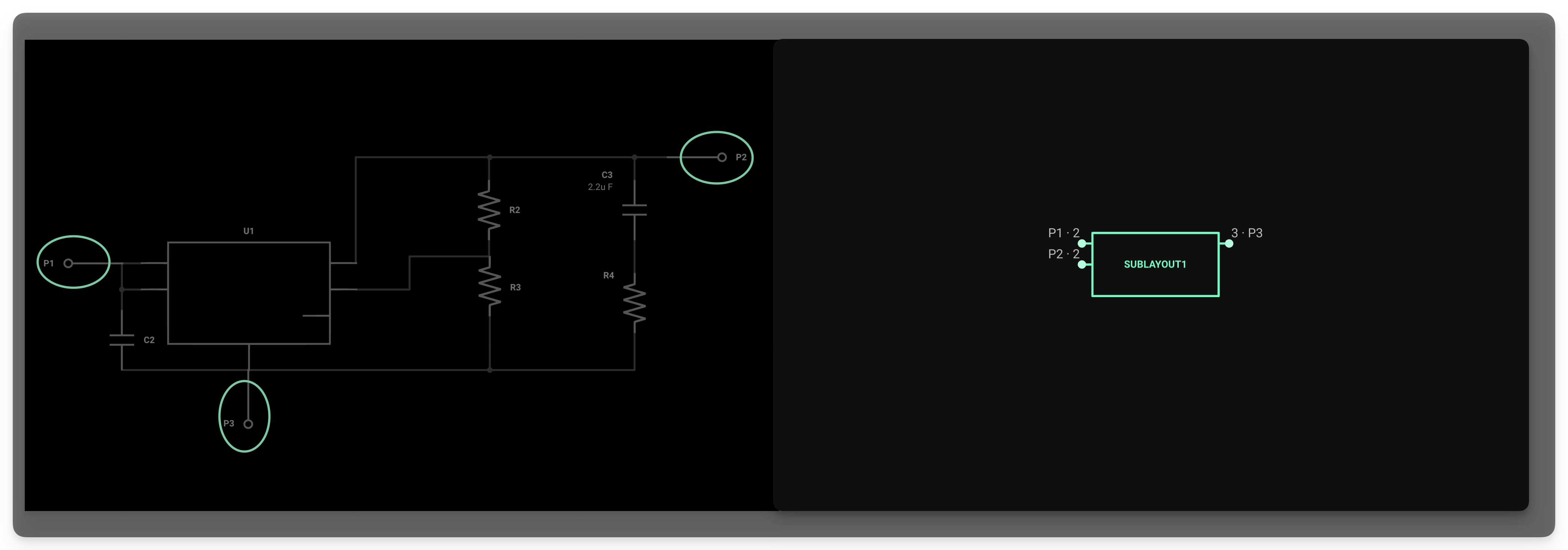
Simply drag the terminals from the library into the schematic editor. You can think of terminals as the inputs and outputs of your module. This means they should be connected to the nets or parts where you expect to connect other components when the module is used.
In this example, we created a module that converts any input voltage to 3.3V. As you see, the terminals are connected to the input and output of the regulator and to ground.
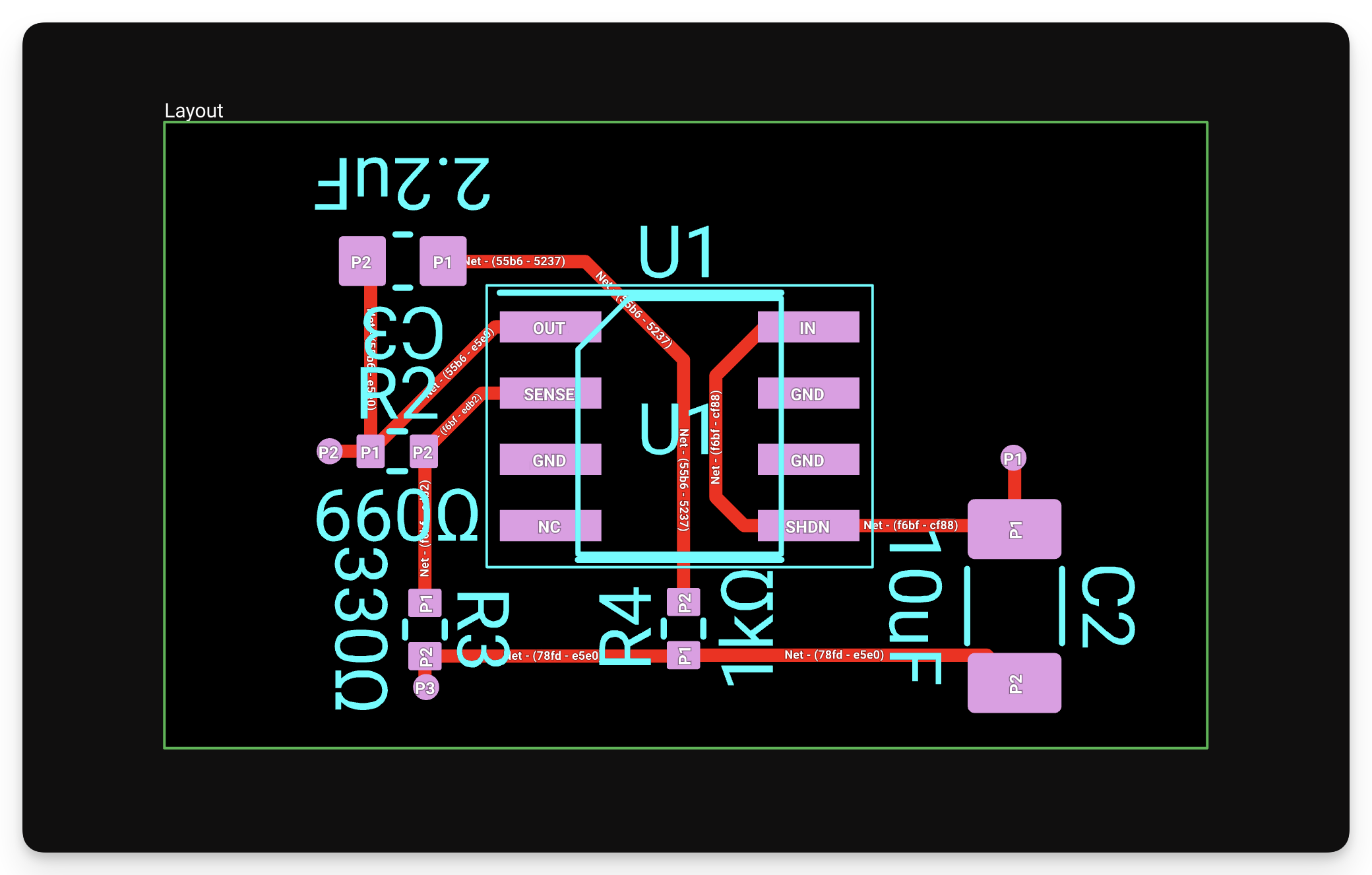
3- Connect the pads in the PCB layout
Once everything is placed and connected in the schematics, open the PCB Editor to begin placing and routing components. Once you open the PCB editor, you'll notice that each terminal has a corresponding pad.
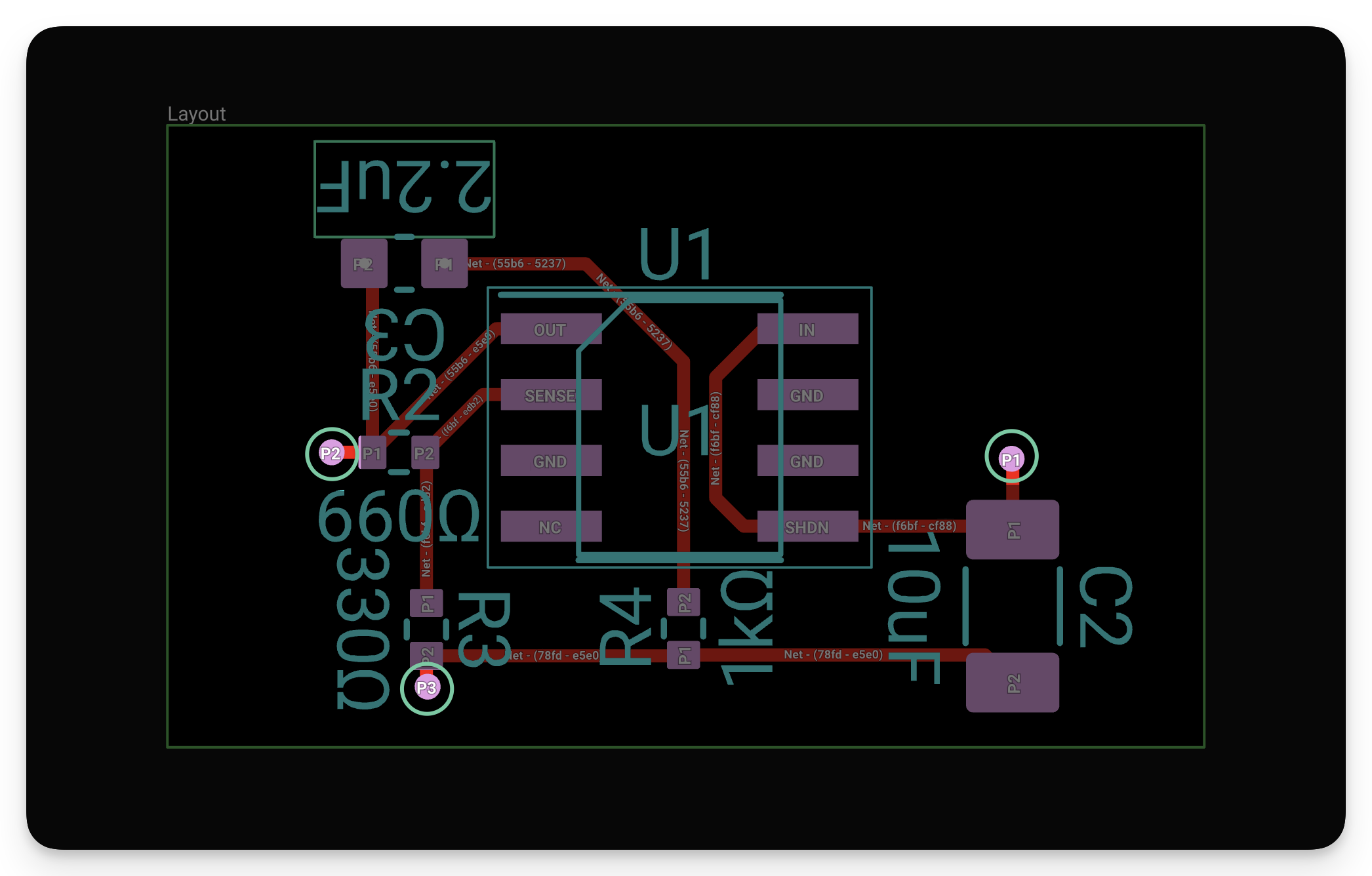
You will route your connections to these points when the module is used in another project. Points P1, P2, and P3 could be placed on pads, through-holes, or vias in the module. For example, we could place P2 directly on the left pad of R2. Once placed, you can add a Size rule to reduce the size of P2 so that it is not excessively large, as shown in the GIF below.
For P1 in this example, it would be a good idea to place two vias connecting C2. This way, it will be easy to route a connection to P1 once the module is used in another project.
Once P3 is placed and resized using the Size rule, the module is complete and ready to be published.The completed example is below.
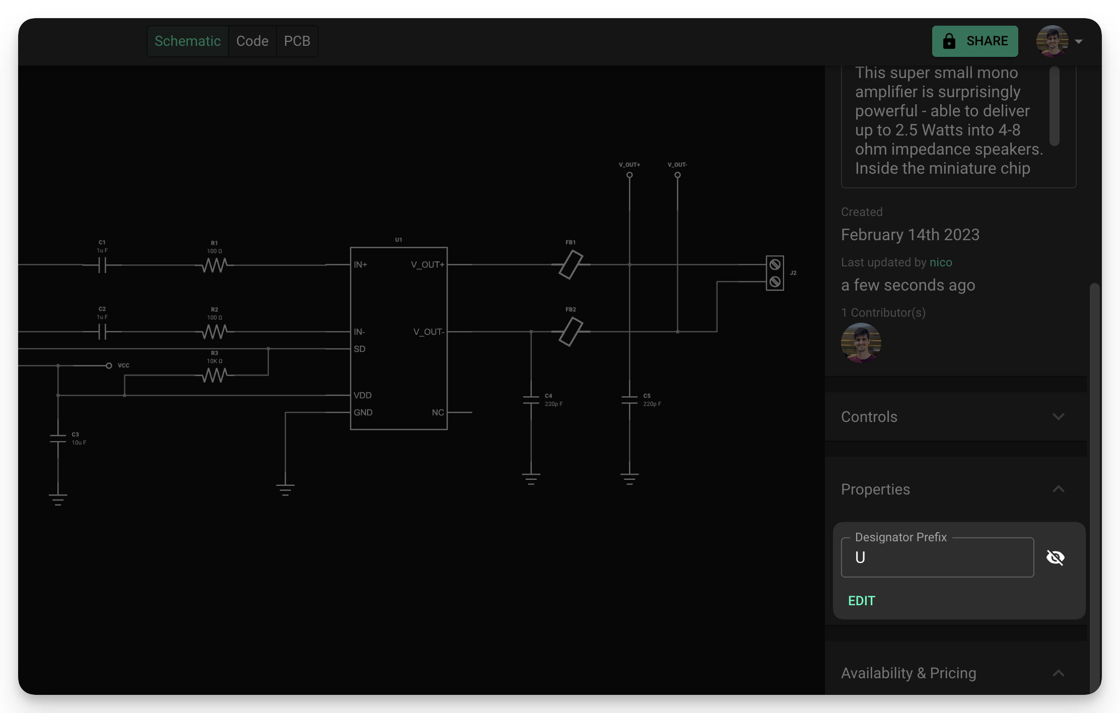
4- Add a designator prefix
It is good practice to add the word “module” to the Designator Prefix Fields, located in the project properties area (right side of the screen). This will make it clear that your project is intended to be a module and make your schematics easy to read. To add a designator prefix:
- Make sure no object is selected by clicking on an empty portion of the canvas
- Find the "Properties" menu on the right side
- Edit the "Designator Prefix" property and add the word "module"
- If there is no such property, you can add one by clicking the "Edit" button below.
5- Publish the Module
The final step is to publish the module to the library. Once the module is published, it can be searched and added to a project. When you drag the module into the schematic editor in a new project, you will see that it will include the module's designator prefix.