Learn how to design modern high-speed applications effortlessly with automatic impedance control and differential pair routing.
Overview
With the increasing complexity of PCB, high-speed routing capabilities have become vital. Impedance control and differential pair routing form the backbone of modern PCB design practices, enabling optimal power transfer and minimal signal distortion through impedance coherence.
Though high-speed design might seem challenging, Flux seamlessly handles the complexities behind the scenes. With automatic integration of impedance and differential pair metadata into components, routing becomes a breeze. Initiating a route for one trace in a differential pair triggers automatic routing for its counterpart.
Automatic Impedance Control
Our library contains a wealth of components pre-configured with optimal impedance and differential pair parameters. This means that you don’t need to worry about any calculations.
Initiate multi-routing by clicking on the routing touch point of either pad in a differential pair, and both traces will automatically route simultaneously. To enhance routing accuracy, Flux mirrors the shapes of the pairs as they depart from and arrive at pads
Routing an impedance-matched differential pair is pretty straightforward:
Drag one or more parts with an impedance-controlled interface (HDMI, USB, etc) from the library.
Wire the parts together.
Navigate to the PCB editor.
Make sure you configure your stackup.
1. We have a few pre-configured stackups from JLCPCB that have been tested in manufacturing.
Click on any pad that belongs to a differential pair net.
Tap the CMD key to route single-ended
On the off-chance that the part hasn’t been configured, here's how to configure it.
You can adjust the final position of any trace by clicking and dragging on a segment
Verifying Impedance and Net Length
Both traces will be impedance-matched according to the interface being routed. You can check the parameters that were used to calculate the trace width and spacing by selecting the target net and viewing its properties. A net length property is also available for quick consistency checks. For verifying net length matching, all you need to do is click on the net.
This covers the majority of what you'll need for advanced routing in most cases. If you wish to add impedance-control support for your own parts or learn about the inner workings of these features, keep on reading.
Under the Hood
Here, we discuss the mechanics of impedance control and how to configure your parts.
Defining Parameters
Pair-matching and impedance requirements are configured by specific properties. Let's explore an example part to understand how it’s configured.
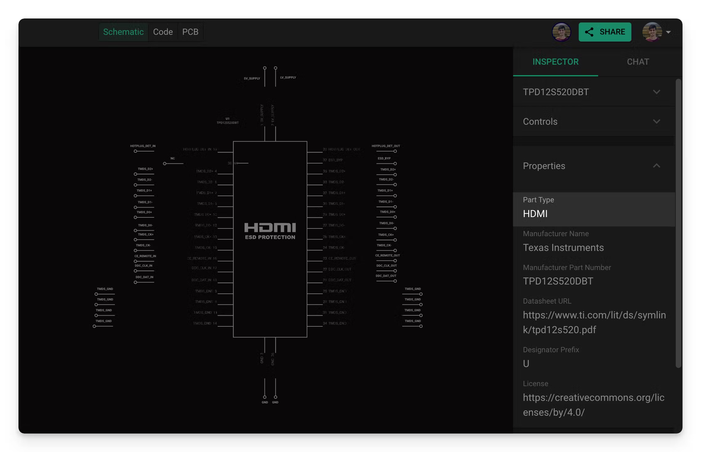
Part Type Configuration
The first thing you’ll notice is that it has a “Part Type” property set to HDMI. Flux will automatically configure the right properties on each terminal when a part is assigned a "Part Type" property that contains an impedance-controlled interface, like HDMI. This automatic configuration requires some prerequisites discussed in the Configuring Components section. In the next section, we’ll discuss a bit more about how each terminal is configured.
Pin Configuration
The majority of the configuration for impedance control takes place at the terminal level. Each terminal needs to be configured with the right parameters. These properties can either be configured automatically by setting up the “Part Type” property, or manually.
Let's break down the required properties using an example: examining TMDS_D2+ and TMDS_D2- from an HDMI interface."
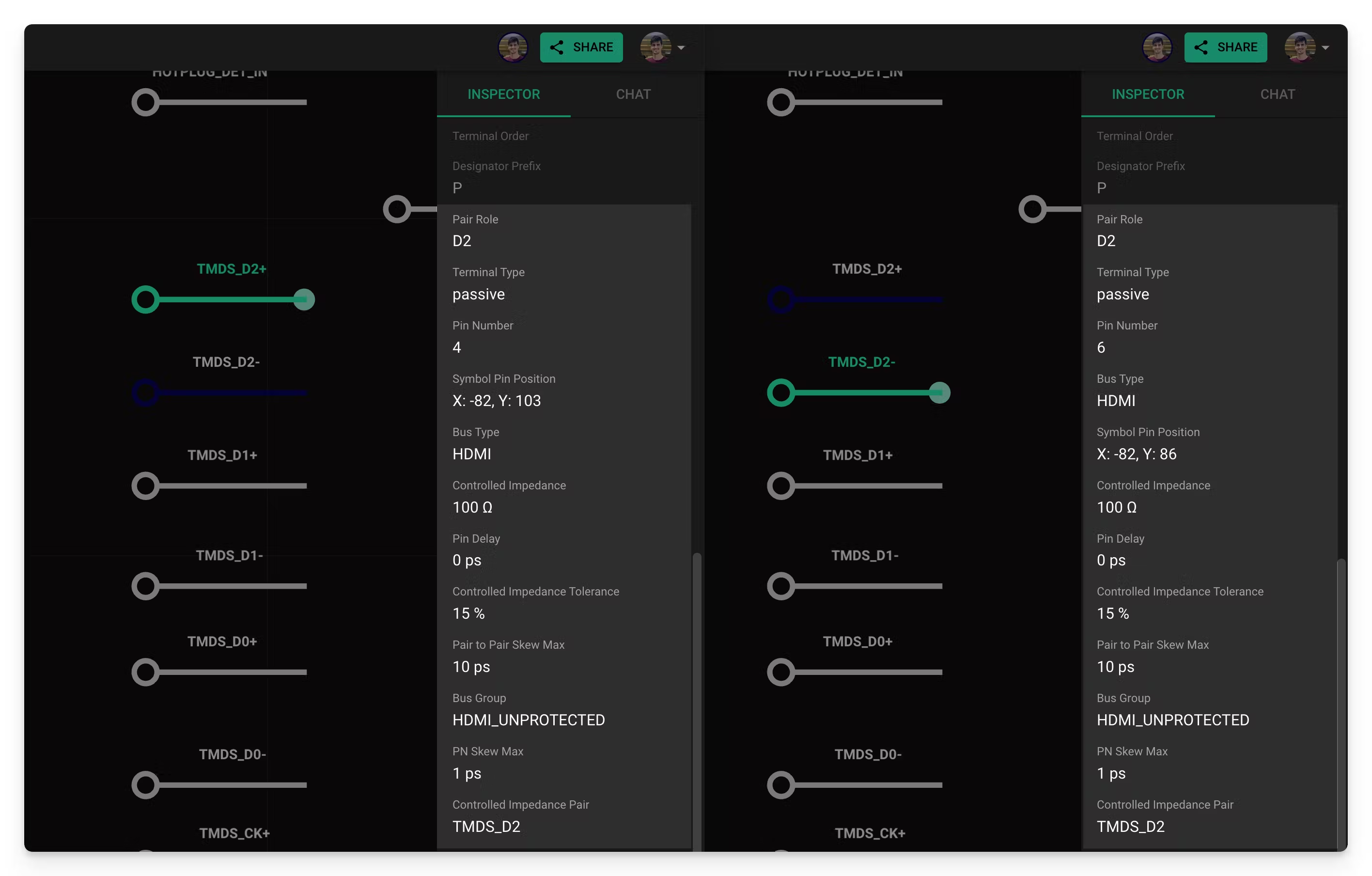
In the picture above, you can see that there are a number of properties that need to be configured. There are two main groups:
Interface parameters (Controlled Impedance, Controlled Impedance Tolerance, Pair-Pair Skew Max, PN Skew Max and Pin Delay): these parameters depend on the target interface. HDMI, USB, and PCIe have different requirements.
Flux parameters (Bus Type, Bus Group, Pair Role and Controlled Impedance Pair): these are internal Flux parameters that define how the different pairs and buses work.
We’ll discuss each parameter in detail in the Manual setup section.
Layout Rules
Let’s now explore what happens when a properly configured part is used in a design.
When transitioning to the PCB layout, the presence of the properties above triggers the automatic generation of certain rules: Keep In, Keep Out, and Trace Width. As a result, differential pair traces are routed with the correct width and spacing, eliminating the need for any manual calculations. This behind-the-scenes intelligence ensures that your designs meet high-speed requirements effortlessly and accurately.
You can quickly check this by adding two of the example parts in a new project and connecting them together. Then go to the PCB Editor and route a few differential pairs. If you select any of those nets, you’ll see a few Layout Rules like the ones below:
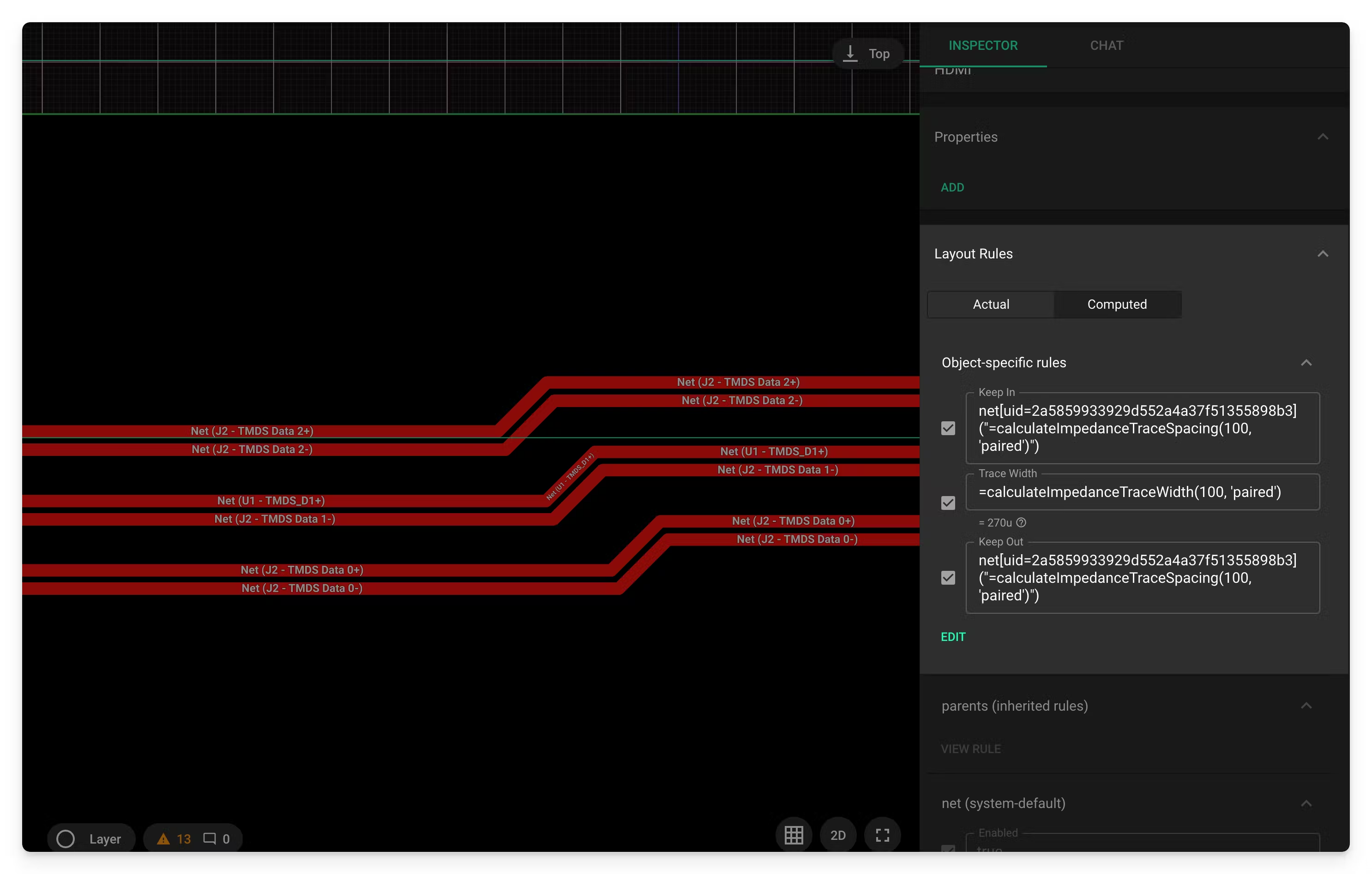
Impedance calculation depends heavily on the stackup used, meaning these rules will change depending on the selected stackup.
Configuring Components
Now that you have a general idea of how the pieces fit together, let’s discuss how to add impedance control and differential pair to a part. There are two ways of doing this:
Automatic setup: this is the recommended process as it only requires part pins to be properly named.
Manual setup: it’s also possible to manually add parameters directly to the pins.
Automatic setup
Flux will automatically add the right parameters to every terminal in the part if the “Part Type” property is set to any of the supported interfaces listed below. This property can be set by the part creator before publishing the part to the library, or it can be added to the part after it has been placed in a project.
Supported interfaces: USB A, USB B, USB C, HDMI, PCIe x1, PCIe x2, PCIe x4, PCIe x8, PCIe x16, Ethernet
Naming Requirements: In order for Flux to automatically match each terminal with the right role in the interface, those terminals need to follow a specific naming convention.
Manual setup
If you’re configuring impedance control for an interface that is not currently supported, you’ll need to add the parameters to every pin manually. This can only be done if you have edit access to the part you’re trying to add support to.
Here's a guide of all the properties that need to be setup.
Examples
Here you have a few parts that have already been configured to use as a reference: