Learn how to create and use custom copper shapes with the polygon feature in Flux.
Overview
Polygons in Flux allow you to create custom copper shapes that are tied to specific nets. This feature is useful for creating:
Custom ground planes
Power distribution networks
RF and antenna elements
Thermal management areas
Signal integrity improvements
Getting Started
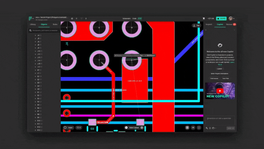
Creating a Polygon
To create a polygon in Flux:
Hover over a pad in your PCB design
Right-click to open the context menu
Navigate to Start Routing Polygon
Click on the canvas to place points for your polygon
Shift while placing points to enable free-angle mode (otherwise points snap to 45° angles)
Right-click to remove the last point
To complete the polygon, either:
Click on the middle of the pad you started from, or
Double-click anywhere else on the canvas

Editing Polygons
Once you've created a polygon, you can edit its shape:
Select the polygon in your design
Double-click on the polygon to enter edit mode
In edit mode, you can:
Click and drag existing points to move them
Double-click on a point to delete it
Hover near an edge to reveal midpoints that can be clicked to add new points
Click on the "Finish Editing" toolbar
Advanced Polygon Shapes
Polygons are normally used to create arbitrary or custom copper shapes. The easiest way of doing so is by using the polygon editing feature as described in the previous section. You can also create polygons with basic shapes provided by Flux, or use SVG syntax to import shapes from other CAD tools.
Basic Shapes
If you want to create a basic rectangular or circular polygon, you can use the shape rule. To create a basic shape:
Create a polygon of any shape using the manual polygon creator as described in the previous section.
Select the polygon and find the Inspect menu on the top right.
Under Object-specific rules:
Click on Edit -> Add
Find and add the Polygon Shape rule.
On the newly added rule, delete the existing data and type rectangle or circle
Keep in mind that the polygon might have moved out of position.
You can also use the size rule to modify the shape
Custom Shapes
If you need to import an existing shape from another CAD tool, you can use it through an SVG path:
Create a polygon of any shape using the manual polygon creator as described in the previous section.
Select the polygon and find the Inspect menu on the top right.
Under Object-specific rules:
Click on Edit -> Add
Find and add the Polygon Shape rule.
Change the existing SVG path for the one you want to import
Multi-Layer Polygons
Polygons in Flux can span multiple copper layers, creating a unified copper structure across your PCB:
Create a polygon as described earlier
Select the polygon and find the Inspect menu on the top right.
Under Object-specific rules:
Click on Edit -> Add
Find and add the Connected Layers rule.
Select the layers you want to connect from the dropdown menu
The polygon will now exist on all selected layers
Via stitching is automatically applied to connect the layers electrically
You can adjust the Fill Stitching Density and Fill Stitching Offset li rules to control the via pattern
You can also manually place additional vias if needed
Multi-layer polygons are particularly useful for:
Creating power and ground planes that span multiple layers
Implementing RF shields that enclose sensitive circuits
Designing thermal management structures that distribute heat across layers
Flux automatically handles island removal for polygons, eliminating any disconnected copper areas that might form during the polygon creation process. This ensures that all copper within your polygon is electrically connected to the net.
Polygon Hierarchy and Priority
When multiple polygons overlap, Flux uses a size-based priority system to determine which polygon takes precedence:
All polygons take priority over Copper fills
Smaller polygons take priority over larger polygons
Polygons of the same net will merge unless they have different properties
This automatic priority system allows you to:
Create complex copper structures with cutouts by using smaller polygons
Implement split planes for different power domains
Design sophisticated RF structures with controlled impedance
Create thermal relief patterns around component pads
Keep Outs and Polygons
Keep Outs can be used to create spacing areas between your polygons and other elements in your project. To add a keep out to a polygon:
Create a polygon as described earlier
Select the polygon and find the Inspect menu on the top right.
You can also select the entire net to apply a keep out to every object in that net. This is specially useful if you have several polygons in the same net.
Under Object-specific rules:
Click on Edit -> Add
Find and add the Keep Out rule.
Select the distance you want the polygon to be removed from other elements.
When a keep outs is applied to a polygon and other elements are present in the keep out space:
If the element colliding with the polygon has been generated by Flux (other polygon, via sitching, etc), said element will be moved respecting the shape of the polygon.
If the element colliding with the polygon has been generated by the user (components, pads, manual vias, etc) the polygon shape will be adjusted to stay away from that element
Tips for Working with Polygons
Simplify shapes: Complex polygons with many points can impact performance
Use with fills: Polygons work well with copper fills to create custom ground planes
Layer selection: Make sure to select the appropriate layers for your polygon
Hotkeys: Use Shift while drawing to toggle between constrained (45°) and free angle modes
Via stitching: Automatically applied for multi-layer polygons, but can be adjusted
Island removal: Flux automatically removes disconnected copper areas within polygons
Related Features
You can also ask Flux for help with creating and optimizing polygons for your specific design needs.