Easily create professional-looking symbols without drawing, or use the advanced tools to create custom-shaped symbols for your PCB designs.
Overview
Flux works slightly differently than other PCB design tools you might be used to. In Flux, parts have two different views: the schematic and the symbol. The schematic view only contains the terminals, while symbols are only visible when a part is placed into a project.
To see a part's symbol at any point in the process, you need to:
- Configure a parametric symbol, or create a custom one
- Publish to the library
- Create a new project and add the part you just published
- This process needs to be repeated every time a symbol is updated
Flux offers two main approaches to symbol creation:
Parametric Symbols
Flux's parametric symbols allow you to better organize your schematic symbols by grouping pins based on functionality and logical connection, all without needing to physically draw the symbol. Instead, by attaching properties to terminals, symbols for parts and modules can organize themselves automatically.
Custom Symbols
Flux's custom symbols provide more flexibility to create advanced or custom shapes for specialized components or to match industry standards.
Parametric Symbols
Parametric symbols can be customized to create different sections within the symbol, group pins, or locate pins on a specific side of the symbol (left or right).

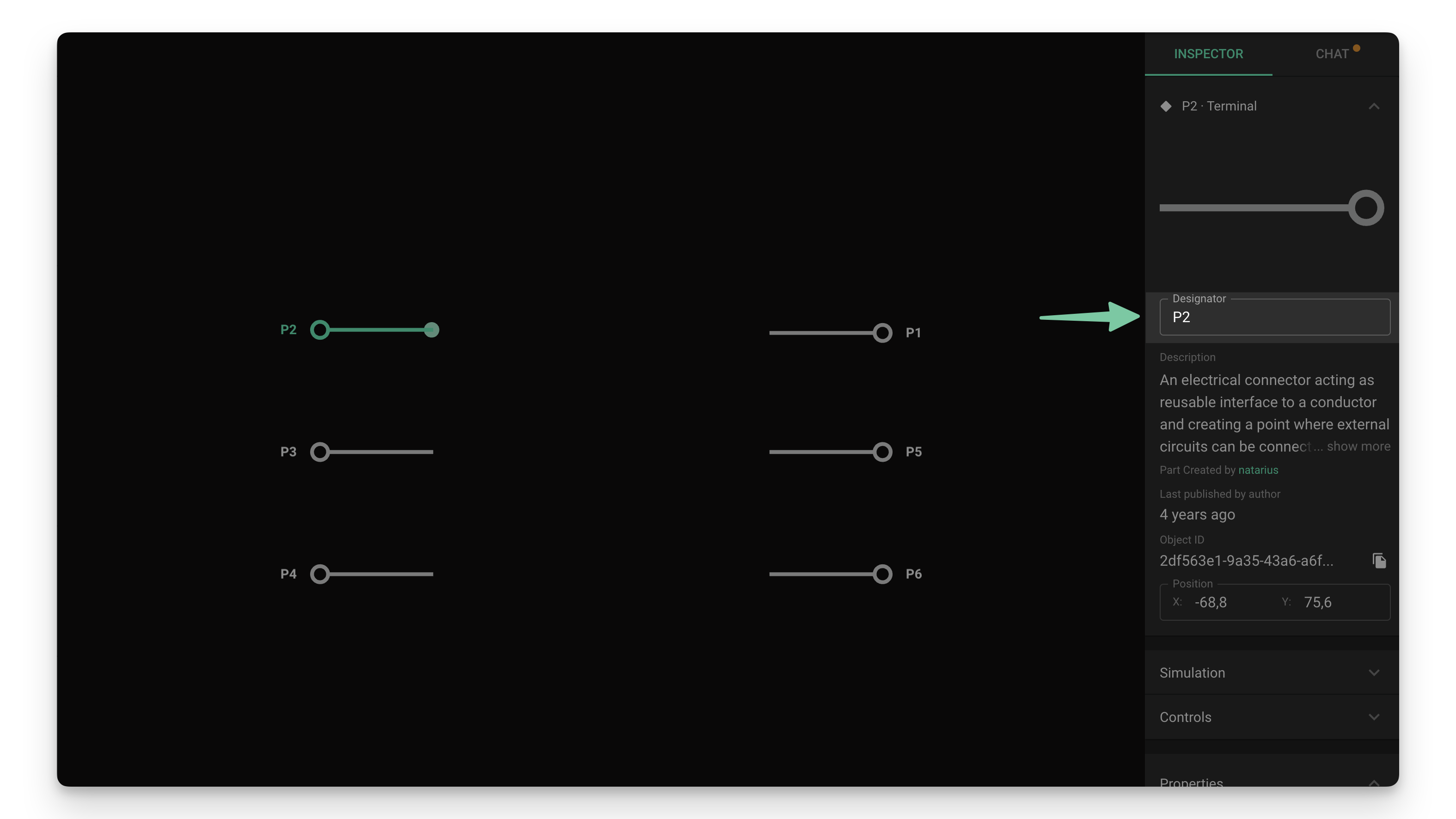
Adding Terminals
The first step in the process is to add a terminal for every pin in your part:
- Use the library menu on the right to find the element called "Terminal"
- Click and drag as many terminals as you need onto the canvas
- Select the newly added terminals and change their designator to match the target pin name
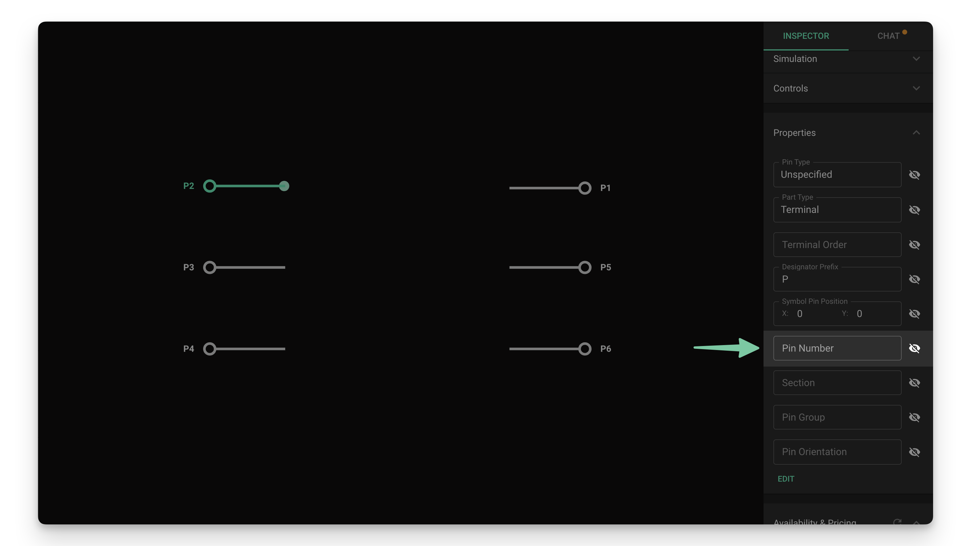
Changing Pin Numbers
To change a pin number:
- Select the terminal(s) you want to edit
- Locate the "Pin Number" property in the inspector menu
- Enter the pin number according to the component datasheet
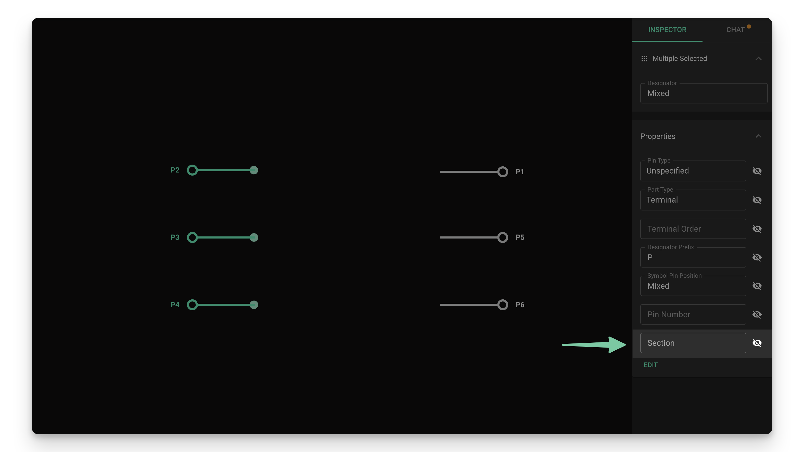
Creating Sections
Sections allow you to create named areas within the symbol to locate related pins. For example, on a microcontroller, one section could be "Power" and another one "GPIO".
Terminals with no section property assigned will all be located in the same empty area.
To create a new section:
- Select all the terminal(s) you want to be located in the same section
- Locate the properties section on the right and click on the "Edit" button
- Add a new property called "Section"
- Type the section name in the textbox
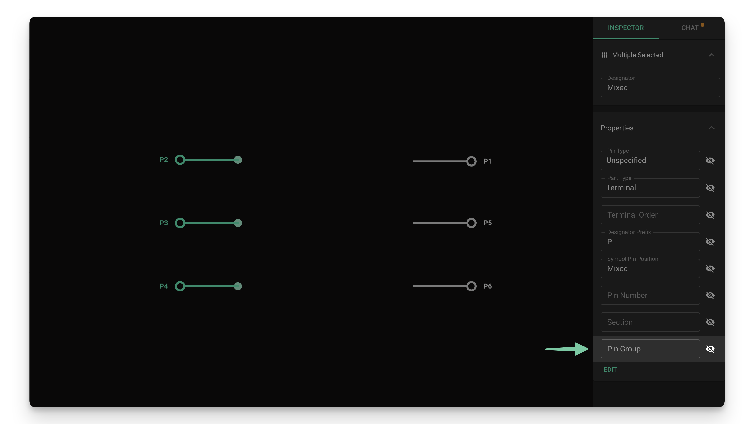
Creating Pin Groups
Pin groups allow you to group together related pins and visibly separate them from other groups. Pins in the same group will be located closer together, and slightly further apart from pins in other groups. For example, within the GPIO section, you can group pins based on register or peripheral.
Terminals with no pin group property assigned will be located further apart from each other and from other groups.
To create a new pin group:
- Select all the terminal(s) you want to be located in the same group
- Locate the properties section on the right and click on the "Edit" button
- Add a new property called "Pin Group"
- Type the group name in the textbox
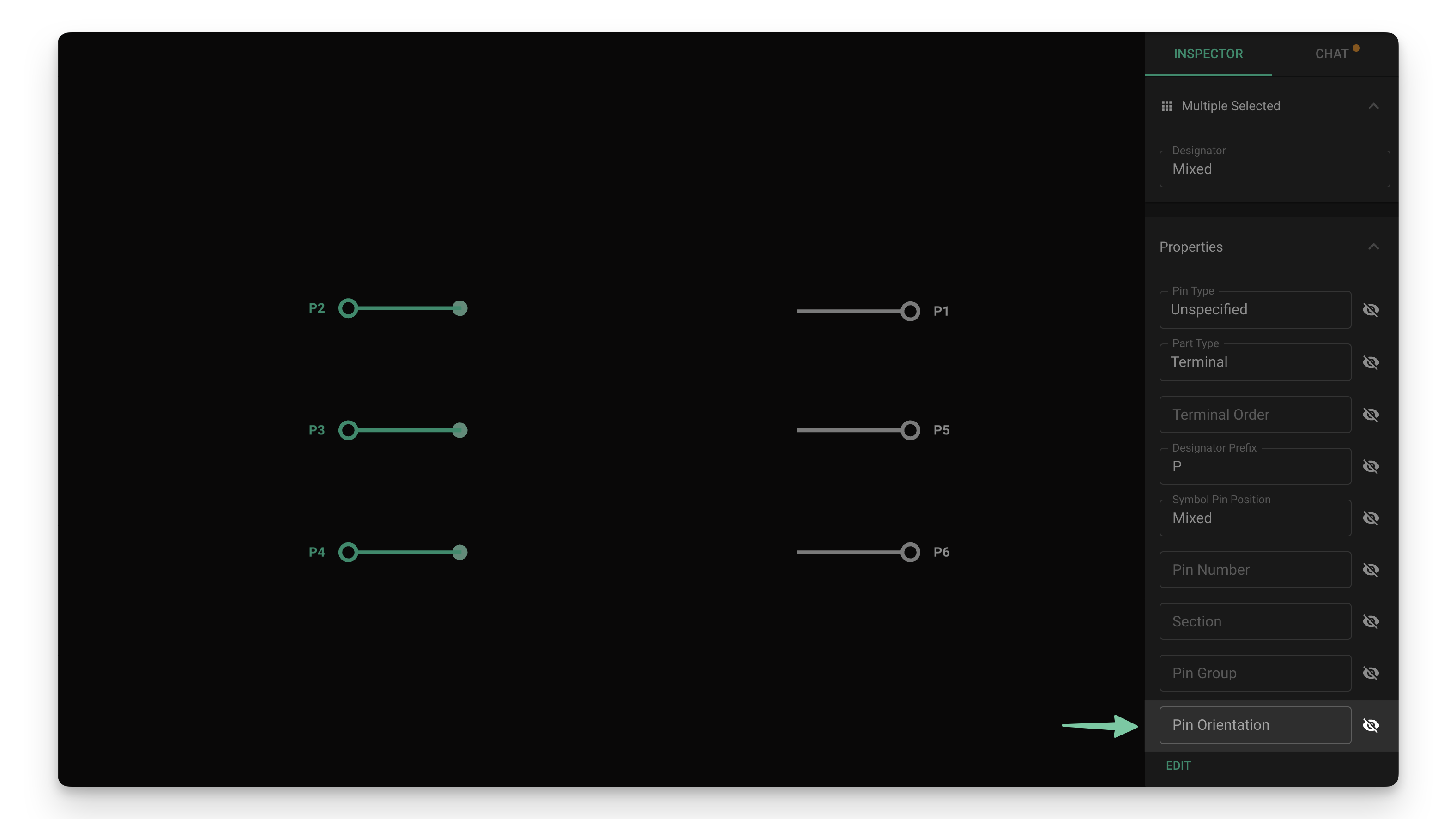
Changing Pin Orientation
Pin orientation allows you to manually locate pins on the left or right side of the symbol.
To change a pin's location:
- Select all the terminal(s) you want to change location for
- Locate the properties section on the right and click on the "Edit" button
- Add a new property called "Pin Orientation"
- Type "Left" or "Right" in the textbox
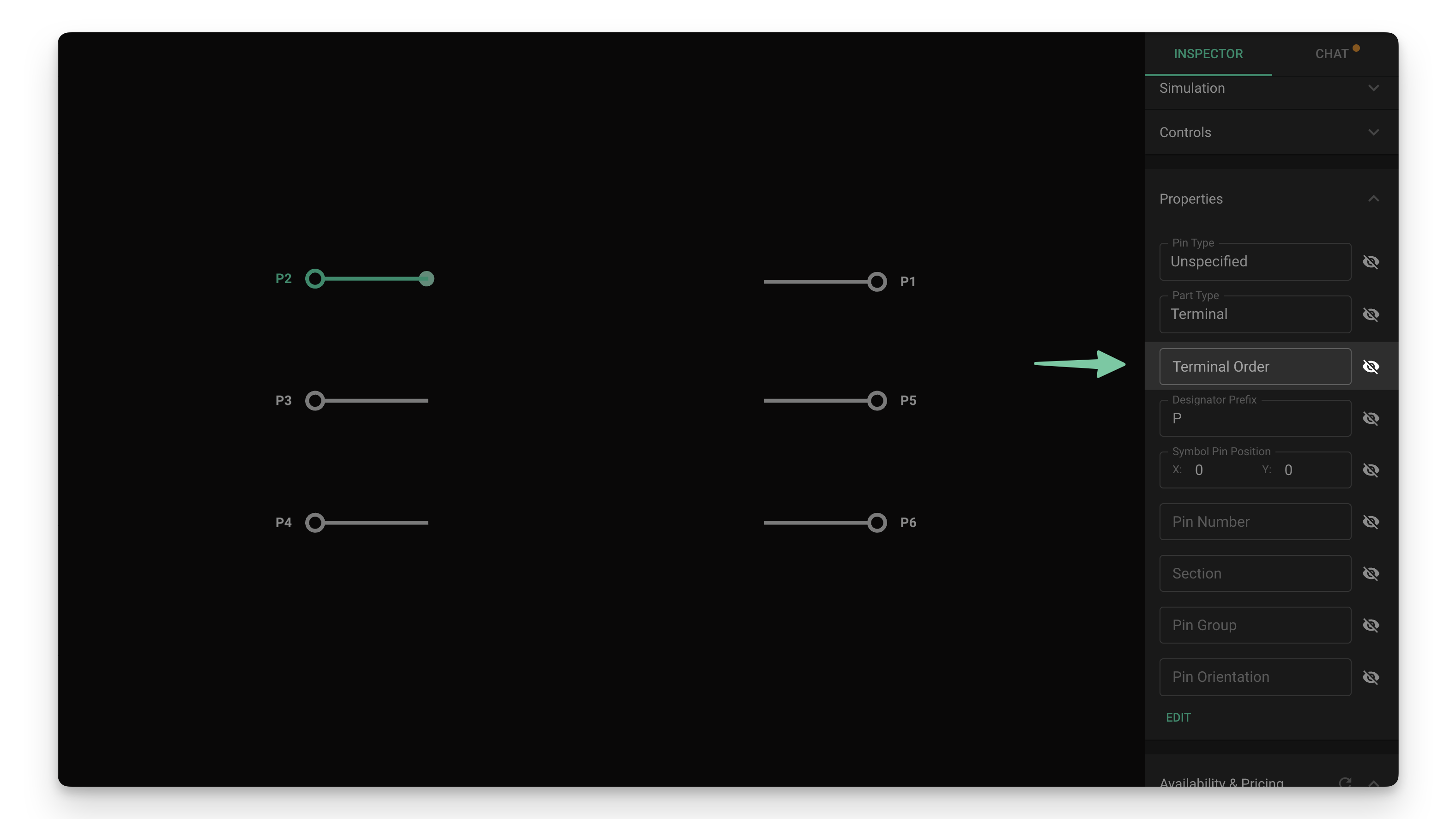
Changing Pin Order
By default, pins will be sorted within their groups/sections in the order specified by the Pin Number. To configure pins in a different order:
- Select the terminal(s) you want to edit
- Locate the "Terminal Order" property in the inspector menu
- Use numbers to set the order. Lower numbers will be placed first
Forcing Parametric Symbol View
Adding any of the properties described above will cause a symbol to be changed from regular to parametric. If you want to force a symbol to look like a parametric symbol without setting groups or sections:
- Open the component and make sure nothing is selected
- Find the inspector menu on the right and locate the Properties sub-menu
- Click on the "Edit" button and add a property called "Symbol Style"
- Set the "Symbol Style" property to "Parametric"
Multi-Symbols
Parametric symbols also support splitting the symbol into multiple parts. This is especially useful to keep designs with high pin-count components clean and organized.
To split a symbol into multiple parts:
- Select all the terminals that you want to put into a different part
- Find the inspector menu on the right and locate the Properties sub-menu
- Click on the "Edit" button and add a property called "Sub-symbol Designator Suffix"
- Type the suffix. Each part of the symbol will be called "[designator]:[suffix]", for example "U1:power" or "U1:1"
Creating a Custom Symbol
If the default parametric symbol does not work for your use case, you can create a custom symbol. We suggest only advanced users try this process as it requires external tools.
Refer to the Custom Pad Shapes tutorial to learn how to create a custom symbol shape. Once you have the asset created and added to Flux, proceed to matching pin locations.
Matching Pin Locations
By default, all terminals will be located at the center of the symbol. To position the terminals to the desired location, there are a few more steps. We've covered this process both in video and written format.
- Publish the part
- Create a New Blank Project and drag the part you're importing.
- You'll notice that both terminals are at the center of the symbol. Now go back to the imported part.
- You'll need to do this process for every terminal in your part
- Select the terminal and find the "Properties" menu in the right-side panel.
- In the "Symbol Pin Position" field, type the desired x and y coordinates for the terminal to sit on the symbol.
- Publish the part and go back to the new project. You'll see a "Update available for your parts" legend in the bottom left. Click on "Review" and accept the changes.
- You'll notice that the terminals have moved. You might need to repeat this process a few times to nail the perfect position.
Best Practices for Symbol Creation
- Follow industry standards: Use standard symbol representations when possible
- Group related pins: Organize pins by function (power, I/O, communication)
- Use consistent orientation: Power pins typically go on top, ground on bottom
- Label clearly: Use descriptive pin names that match the datasheet
- Split complex components: Use multi-symbols for high pin-count devices
- Maintain proportions: Keep symbol size proportional to pin count
Troubleshooting Common Issues
Symbol Not Appearing
- Verify that you've published the component to the library
- Check that you've created a new project and added the component
- Ensure that symbol properties are correctly applied
Pin Organization Problems
- Verify that section and pin group properties are spelled consistently
- Check that pin orientation is set correctly (Left/Right)
- Ensure pin numbers match the datasheet
Multi-Symbol Issues
- Verify that the Sub-symbol Designator Suffix is applied to the correct terminals
- Check that each sub-symbol has a unique suffix
- Ensure that related pins are grouped in the same sub-symbol