Simplified HDI design with automatic selection and placement of optimal via types and configurations.
Overview
In traditional PCB design, designers are required to select the appropriate via type for each connection, which can be challenging and prone to errors, especially in multi-layered boards. Flux simplifies this process by automatically determining the optimal via configurations and applying them where needed.
For example, if you need to connect a trace from mid-layer 2 to the top copper layer, Flux's Smart Vias feature allows you to select the start and end layers, and it will automatically place the necessary vias and adjust the layout
Getting Started
Smart vias will automatically be in use when blind, buried or microvias are configured. To configure these kind of vias, please refer to this documentation page.
How is the Right Via Selected?
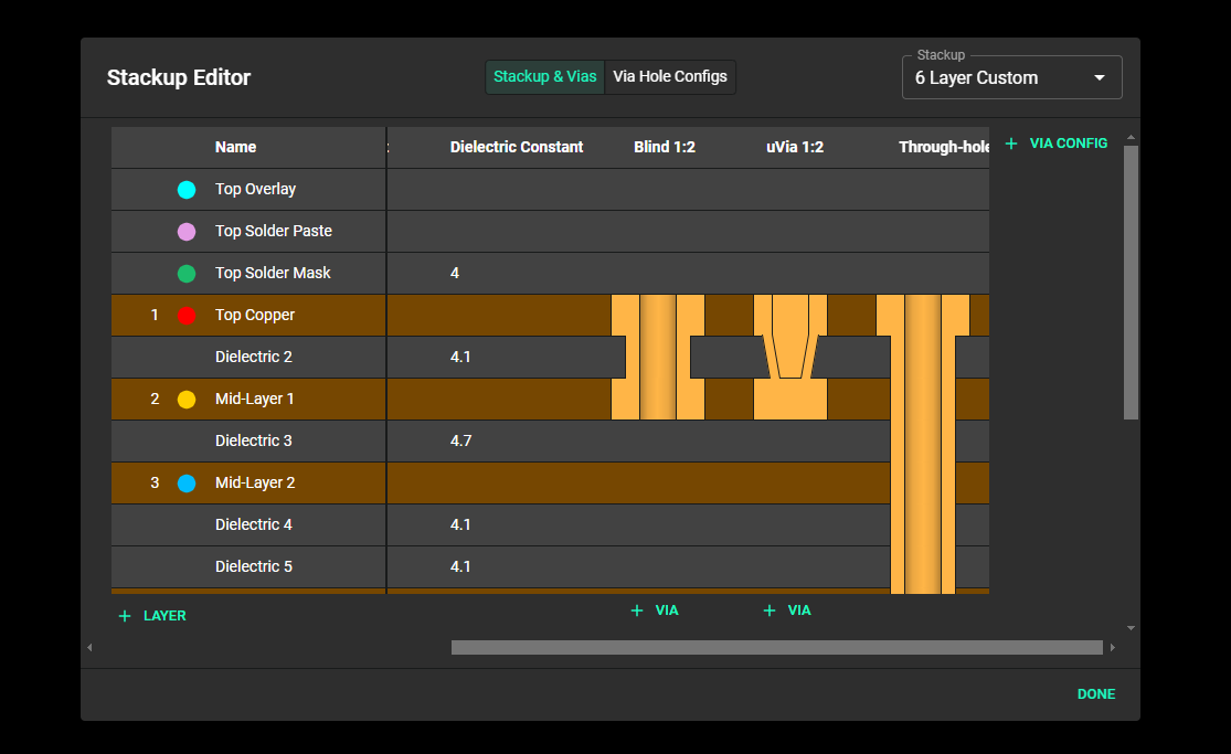
After adding all the via configs you will be using in your design, selecting the right via for a particular layer transition is a matter of prioritization. Let us assume you have a stackup that has 3 via configs;
Blind 1:2
uVia 1:2
Through-hole via
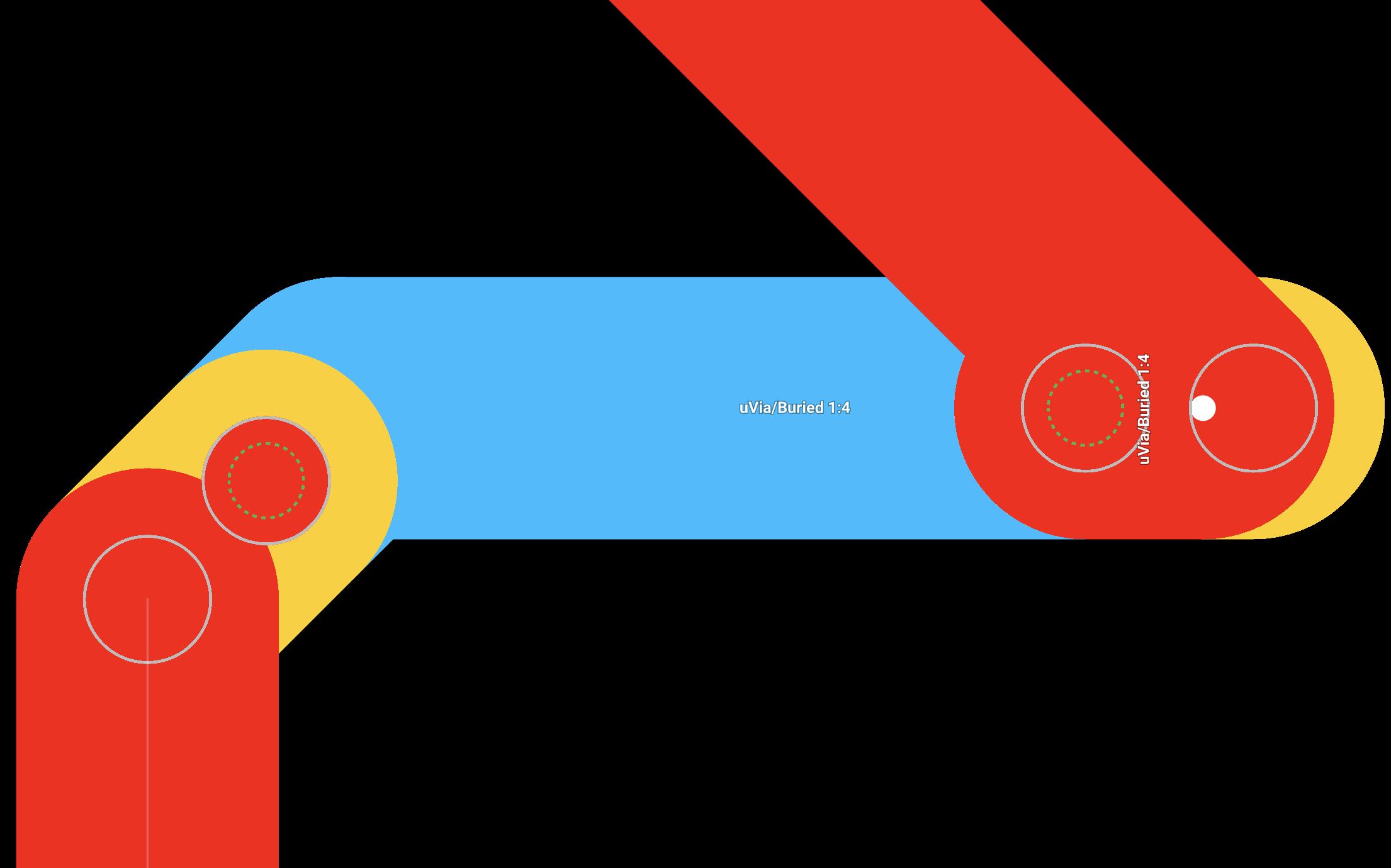
As shown below
If you want to use uVia 1:2 instead of Blind 1:2 during routing, you would do this in two steps
You would place a via while on the Top Copper by right clicking on the canvas, selecting the Mid-Layer 1 from the layer menu that appears and then finishing the trace.
Select the via placed, a toolbar will appear, you will then click the "via options" which will be the drop-down on the far right of the toolbar. Finally you will remove the Blind 1:2 via from the list by clicking it. You will notice that the via visualization changes indicating you are now using the desired uVia 1:2 configuration.
Changing Via Type Priority
When setting up your via configs, it is important to remember that the order in which the via configs exists in your stackup is directly related to the priority of those via configs. Via configs on the far left have high priority while via configs on the far right have low priority. This means that when transitioning from one layer to another, Flux will first attempt to use the via config with the highest priority. If that config isn't suitable due to some design rules, manufacturability constraints, or layer restrictions, it will then proceed to the next via config in the order of priority until it finds a suitable one. If no suitable via config is found, Flux will default to the Through-hole via.
Changing priority of your via configs is as simple as hovering at the top of the via config, where the name of the via config is and dragging to the left to increase its priority or dragging it to the right to decrease its priority.
Advanced Rules
There are 4 rule that affect smart vias, these include;
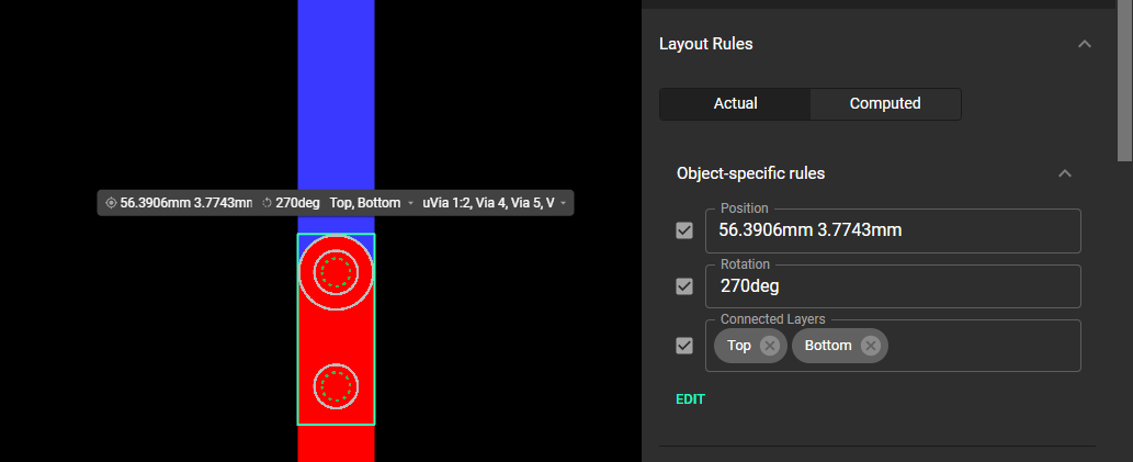
Rotation rule
Via Options rule and
Users can configure the way smart vias are laid out and operate by modifying any of these rules from either the toolbar or the inspector panel on the right side
Keep-Out Rule
This rule dictates the minimum hole-to-hole distance between vias. The default distance is set to 250 microns, but you can adjust this value to meet specific design needs. Increasing this distance means the Smart Via engine has to put vias farther from each other, while reducing it allows for a more tightly packed layout.
Rotation Rule
This rule controls the angle of staggered via configurations. By default, Smart Vias rotation angles are automatically computed to best suite the design, but this can be changed to other angles, such as 180 degrees, depending on your design requirements.