Silkscreen
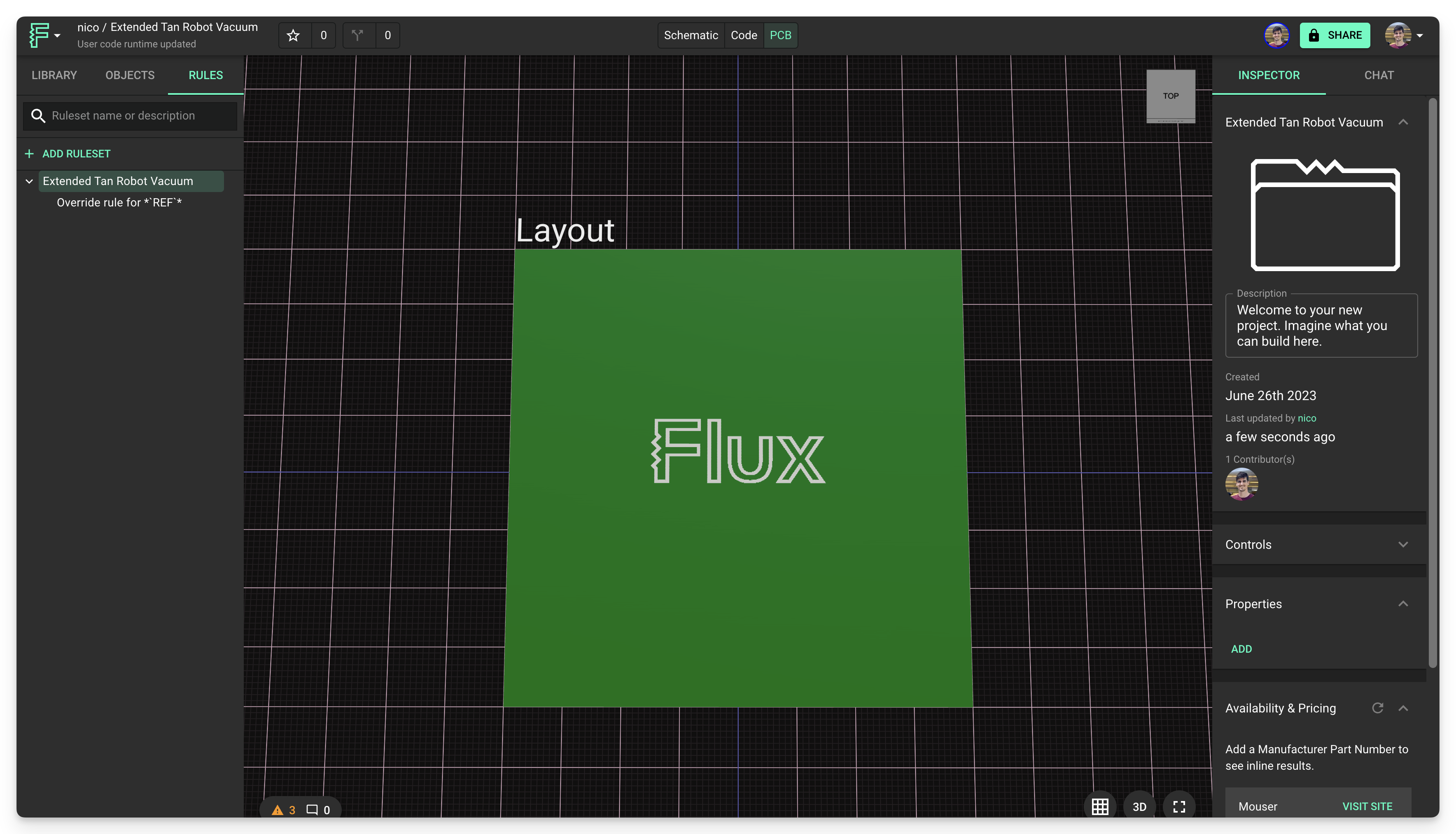
Silkscreen elements are one of the most basic elements in Flux. It's a layer of ink traces used to identify components, test points, parts of the PCB, warning symbols, logos, marks, etc.

Overview
In this section we'll cover:
Adding silkscreen elements
- Text
- Silk Line
- Silk Circle
- Silk Rectangle
Modifying existing silkscreen
Creating custom silkscreen
Adding Silkscreen

Silkscreen objects are ink traces used to identify test points, components, warning symbols, or any additional desired graphical element on your PCB
To add a silkscreen element:
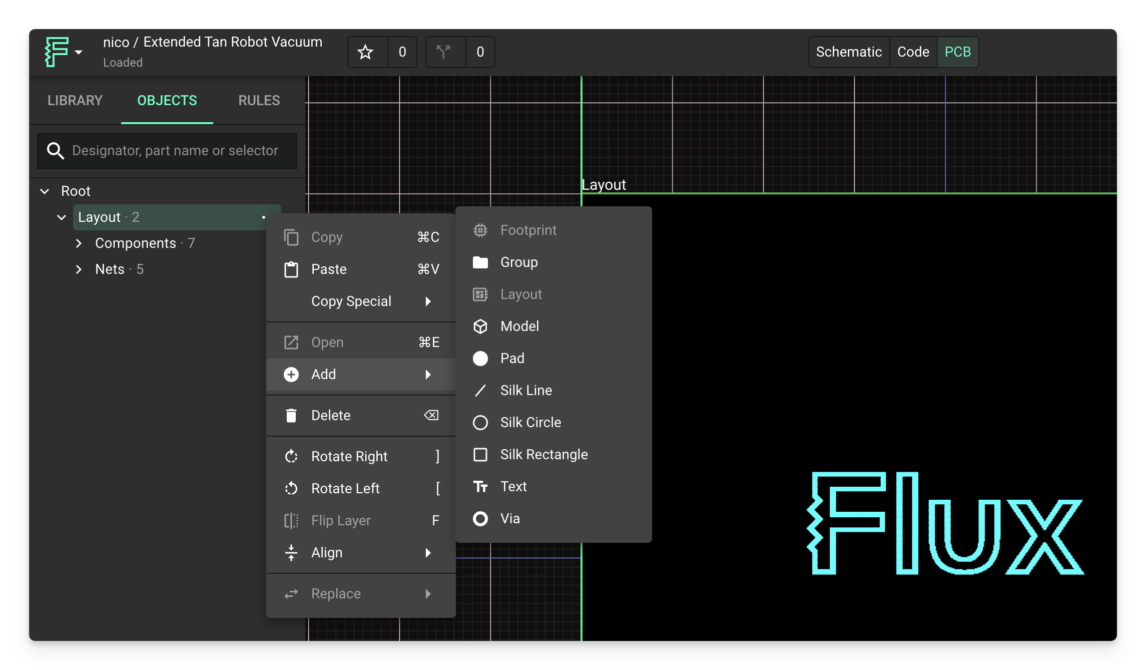
- Left-click on the Layout object in the objects tree to ensure it's selected
- Right-click > Add > Silk Line / Silk Circle / Silk Rectangle
A silk text is a particular kind of silkscreen that lets you add text to your PCB.
A silk line is a line that stretches between two specified points. You can use a line path rule for any desired curves.
A silk circle is a circle with a specified origin and diameter.
A silk rectangle stretches between two specified points.
The stroke length, spacing, style, width, and width of these three silk elements can all be modified using the appropriate rules.
Modifying Existing Silkscreen
The tutorial below covers how to customize or modify existing silkscreen elements of components in Flux. For example, repositioning or hiding silkscreen content of a component that you've imported from the library or another tools.
Moving and Hiding Silkscreen
Example 1: Hiding the silkscreen element of capacitor.
- First select the individual silkscreen element that you'd like to modify. Hovering over the component and left-clicking selects all of it. Instead, double-click to select the individual element within the component, or find it in the object tree, or hover and press the command key to select the element directly.
- Once you've selected the silkscreen element, move it from its default position. In doing so, Flux will automatically generate a new
positionselector-rule with an!importantflag. The only way to modify individual elements (silkscreen content, pad, etc.) within a component is by using the!importantflag. - To hide the element once Flux has auto-generated a
positionrule with!importantflag, add an additionalenablerule and set it tofalse. To force the element to be hidden, add!importantto it as well.

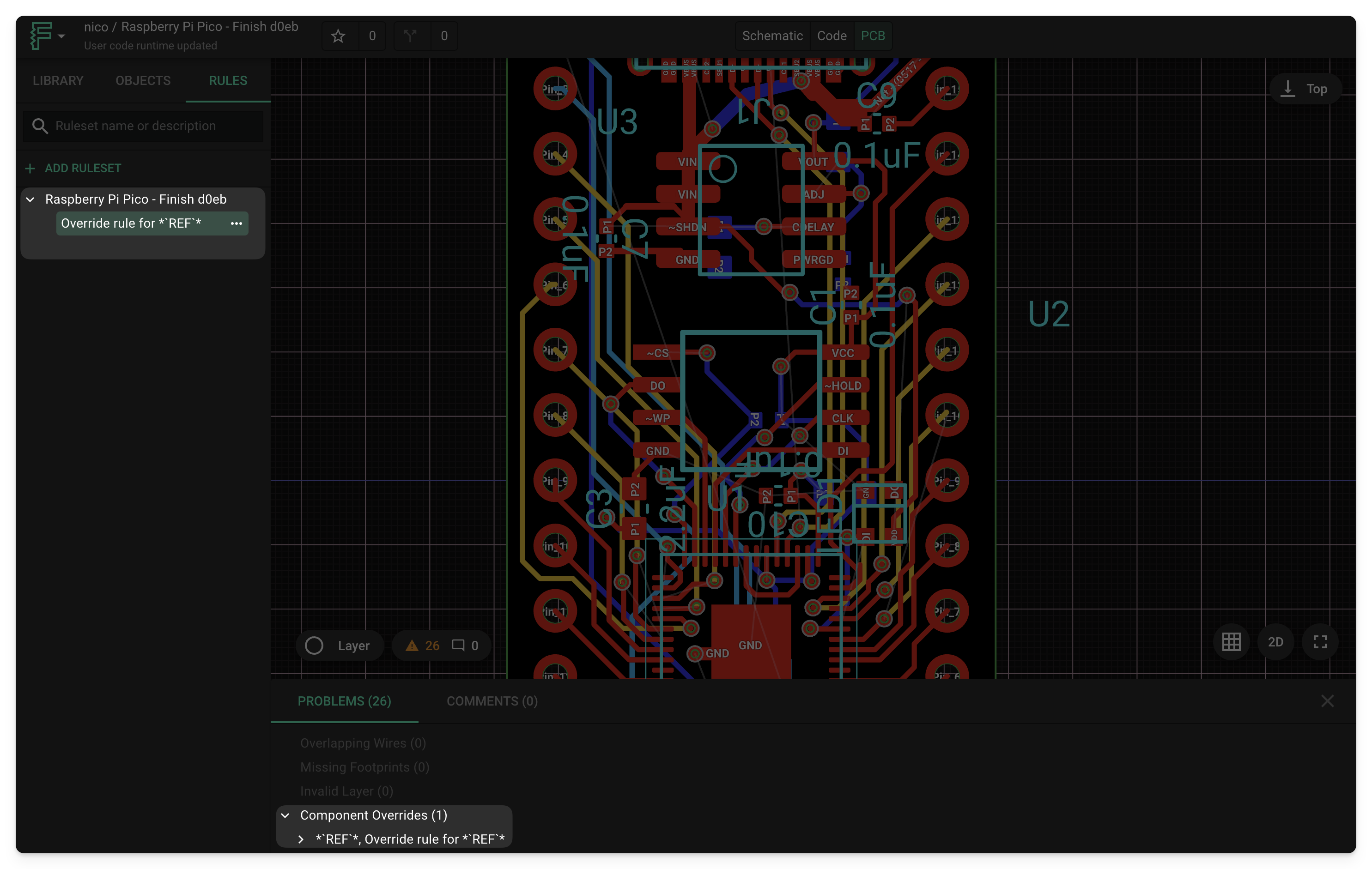
Adding a component override rule allows you to make modifications with the !important flag.
Through this process you can hide any element you desire. As the positionrule is no longer necessary, feel free to delete it. If you only care to change the position of the silkscreen content, rather than hide it, skip step 3.
Modifying Silkscreen in Bulk
Through this process you can modify a group of elements, such as hiding all the silkscreen VALUE elements of all components in a design. Rather than selecting them all, it's easier to do in bulk.
- First, notice that all elements have the word
VALUEin a designator. Therefore, add selector-based rule with selector criteria set to[name*="VALUE"]. This selects all the value silkscreen elements in the design allowing you to add an applicable rule to them all. - Then, add an
enablerule set tofalseand add the!importantflag. This will hide all the VALUE elements
For a more complex example, consider hiding all VALUE elements of only resistors in the design.
- Simply add a selector based rule with the following syntax:
*[PartType=Resistor][name*="VALUE"]`` . - Then, as above, add an
enablerule set tofalseand add the!importantflag.
Creating Custom Silkscreen
In creating a new part, you can add an .svg as a symbol. For example, notice that all parts in the library have an .svg for the symbol. You can use also add an .svg file to your project to create custom graphics to your board through a silkscreen.
If you want to learn more about creating custom silkscreen shapes, we have a full custom shapes tutorial.
Alternatively, feel free to use our community library to search for premade graphics! For example, you can simply add the Flux logo by finding it in the library search and dragging it in.