Trace width can be defined at trace, net, or global levels, giving users complete flexibility in the final design.
Overview
Different designs have completely different trace width requirements. Flux provides complete flexibility to configure trace widths at any different level, from single trace segments to several nets at once.
Configuring trace width on a single trace segment
In some cases, only a single trace segment needs to have a specific width.

Changing the trace width for a single trace segment will override any other value set at net or global (selector) levels. Learn more about rule precedence here.
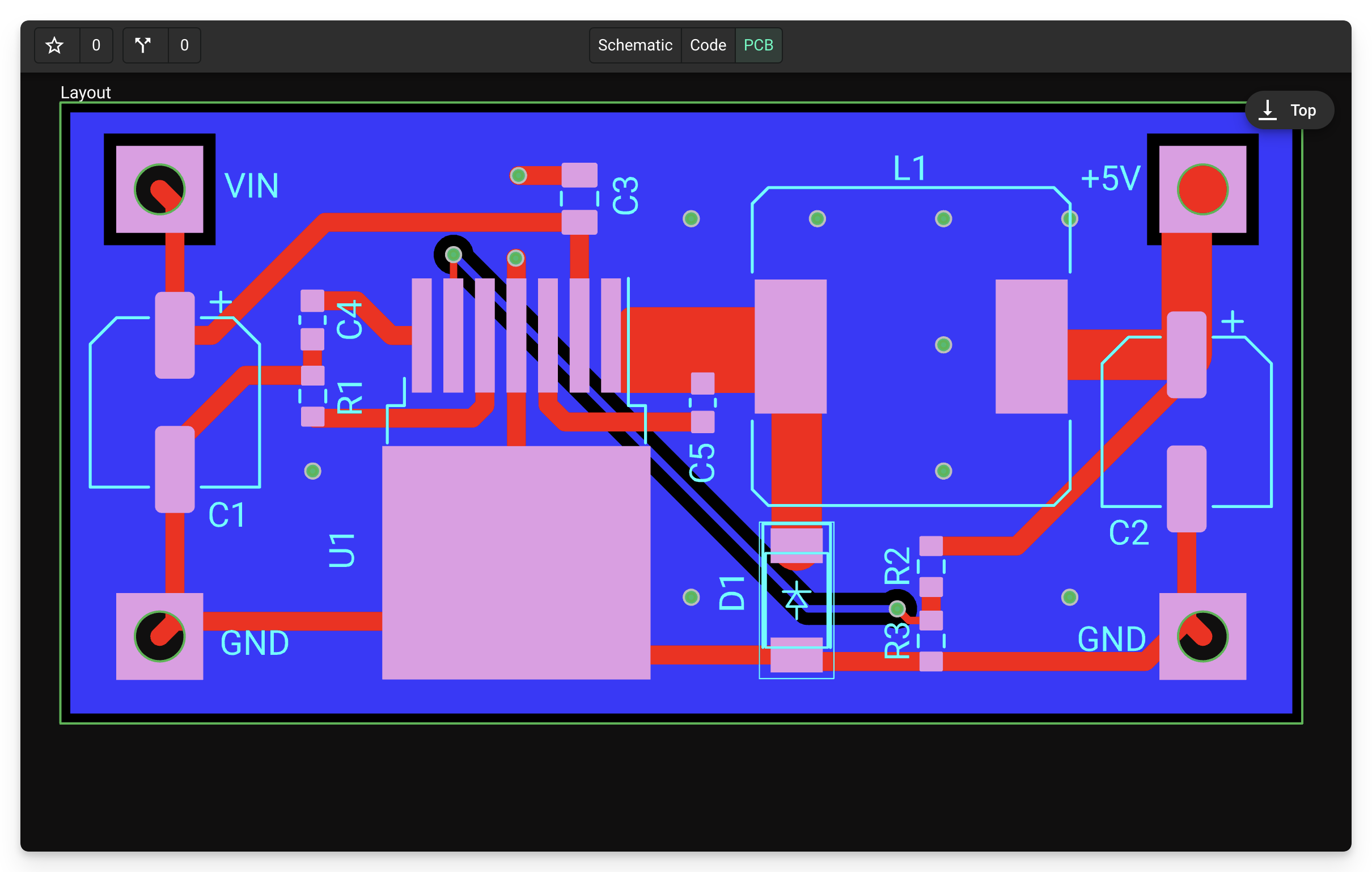
Navigate to the PCB Editor
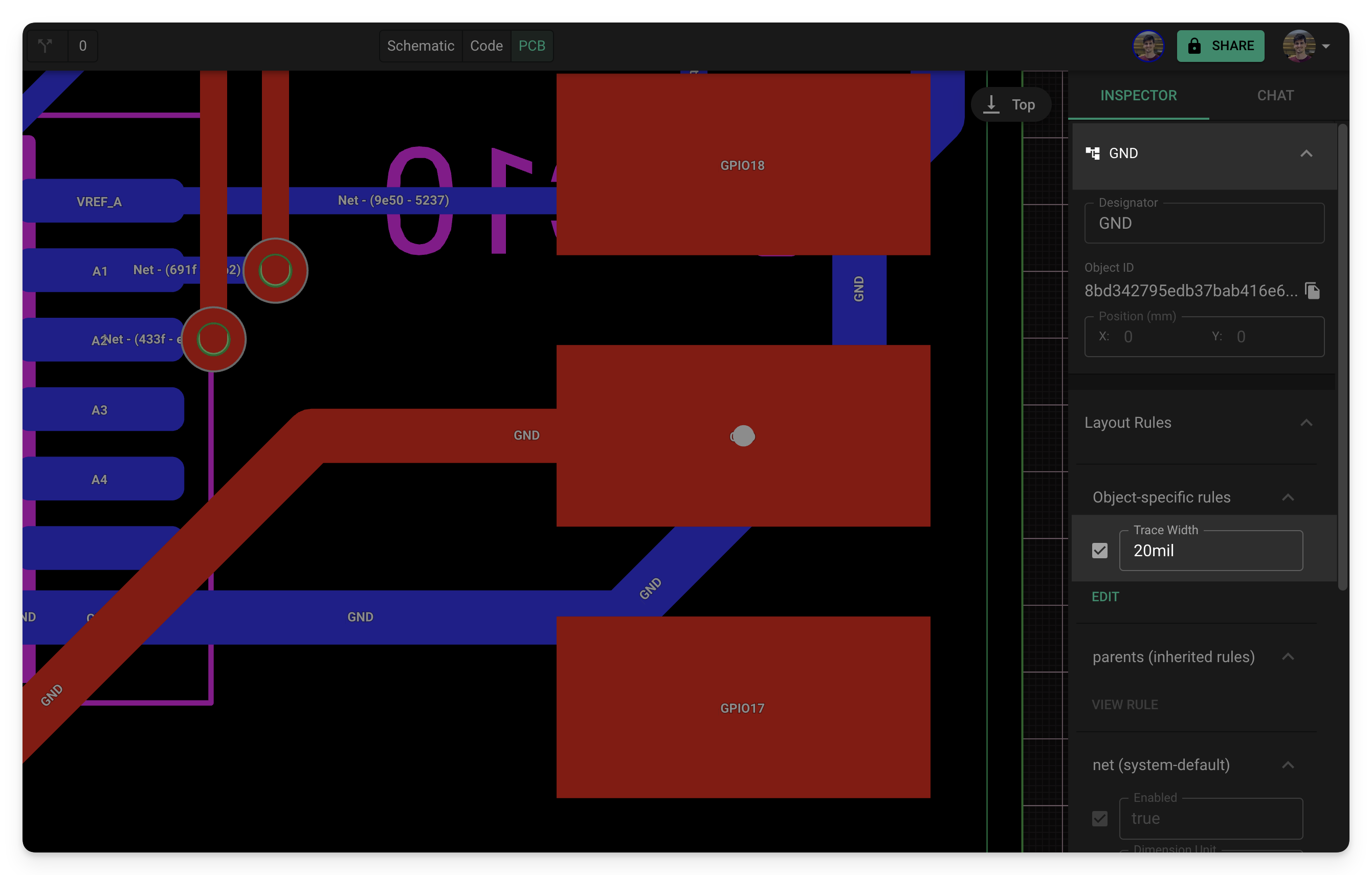
Select the trace segment you want to modify the width.
In the right-hand panel, navigate to "Object Specific Rules".
Select the "Edit" button and then select "Add".
Search for
Trace Widthin the rule selector and select "Add".- You can also add "
Trace Width MaximumandTrace Width Minimumto further constrain the width.
- You can also add "
In the property's field, enter the desired trace width.
Configuring trace width at net level
Setting up trace width at a net level ensures that every trace segment in that net will have the correct width.
Navigate to the PCB Editor
Select "Objects" on the left panel and select the net node you want to modify.
- Tip: It can be helpful to rename the nets using the designator for quick future reference.
In the right-hand panel, navigate to "Object Specific Rules".
Select the "Edit" button and then select "Add".
Search for
Trace Widthin the rule selector and select "Add".- You can also add "
Trace Width MaximumandTrace Width Minimumto further constrain the width.
- You can also add "
In the property's field, enter the desired trace width.
Configuring trace width using rule selectors
Selectors provide more flexibility to configure trace width at different levels. You can use selectors to configure several nets at once, several trace segments, or any combination.

To change the width of several nets:
Navigate to the PCB editor.
Select "Rules" on the top left panel and "Add Ruleset".
Select the new ruleset, and in the right-hand panel, name the ruleset via the designator at the top.
In the "Selector" tab, add the designators of the nets you want to modify the trace width.
- As shown in the example above, you can select nets using the "#" operator. You can also rename nets by bringing up the context menu for objects in the object panel.
- Check out Selector-Based Layout Rules to learn more about using selectors.
In the "Layout Rules" tab, select the "Edit" button and then select "Add".
Search for
Trace Widthin the rule selector and select "Add".- You can also add "
Trace Width MaximumandTrace Width Minimumto further constrain the width.
- You can also add "
In the property's field, enter the desired trace width.
Trace and Net-Related Specific Rules
Flux contains other related rules that allow you to customize further the behavior of traces and nets, listed below. See the complete list of rules for further information and examples for using each.
- Fill stitching density: creates vias in a ground or power net fill, known as fill stitching.
- Fill stitching offset: allows for offsetting fill stitching.
- Preferred trace width: allows for presetting trace widths for easy toggling during routing.
- Trace shape: defines the shape of a trace, either curved or arced.
- Trace width: sets the width of a trace (or collection of traces).